


ELECTRICAL
Updated 12/16/2018
Couple of useful docs:
VPX assignments.

My wiring assignments for the three 3-core wires I'm using.

Updated 11/30/2018
Updated 9/13/2018
Updated 11/10/2017
I made a spreadsheet to keep track of all the connections I need to make with regard to the panel, etc.
Let me know if you'd like a copy.
Let me know if you'd like a copy.
Updated 9/13/2018
I found this useful presentation on best practices for electrical work.
Updated 11/10/2017
At this point I've read both Bob Nuckolls book "Aeroelectric Connection" and Marc Ausman's "Aircraft Wiring Guide" and I recommend both. Bob's book is in-depth and about all aspects of electrical systems for experimental aircraft and Marc's is a much shorter book that is right to the point of what you need to know at a practical level. He covers both a traditional approach and an approach using the Vertical Power systems (he's the founder of the company, though he no longer owns it).
Based on what I've read, I'm definitely going with the Vertical Power approach. It's not much more money than the traditional approach, it greatly simplifies the wiring, uses high reliability electronic circuit breakers, it provides a huge amount of electrical system data/intelligence to your EFIS (current draw, voltages, various types of faults, etc.) and it adds a lot of safety because of the sophisticated fault detection and EFIS integration. In my opinion, it's a no-brainer. Check out the products here.

There are two systems available, the VP-X Sport and Pro. The Pro provides more 5A/10A circuits and more importantly it has what they call DualBuss Technology. That provides for 2 power busses and 2 microprocessor controllers in one box. I haven't decided which way to go on that, though I'm leaning toward the Pro.
The Rotax engine has an 18A generator as standard and an optional 40A external alternator, which I assume I'll need. As you might expect people use the 40A as the main alternator with the 18A as backup.
One important thing I got from the Nuckolls book is the correct solder to use: Kester 44 63/37.
I've been working with the VP Online Planner, which is great, and here is what I have entered so far.
See further down below for more info on the wiring and the type of wire I'll be using.
NEW: Found another good source of knowledge on aircraft wiring. Check it out here.
AVIONICS
I am planning to have my plane IFR certified, so it will require a certified navigator along with being robust and redundant. Here's my current thinking for the panel (minus the switches): All Garmin, using one screen of the Garmin G3X Touch, one iPad Pro and the Garmin GTN 650 Navigator as the main pieces of the panel. I'll also use the Garmin G5 as a backup.
Current Panel Idea


Here's my panel's primary and backup functionality:
| Function | Primary | 1st Backup | 2nd Backup |
|---|---|---|---|
| Airspeed/Altitude/VS | G3X | G5 | iPad Pro (GPS-Based) |
| Attitude/SynVis | G3X | G5 | iPad Pro (Distinct HW/SW for all 3!) |
| VFR Nav | G3X | GTN650 | iPad Pro (3rd Backup: iPhone) |
| IFR Nav | GTN650 | G3X | iPad Pro |
| Weather (ADS-B) | iPad Pro (Separate ADS-B In) | G3X | GTN650 |
| Traffic (ADS-B) | G3X | GTN650 | iPad Pro (Separate ADS-B In) |
| Terrain/Obstructions | G3X | GTN650 (?) | iPad Pro |
| Engine Monitor | G3X | -none- | -none- |
| Comms | GTN650 (Com1) | G3X (Com2) | Handheld |
The engine monitoring will only be via the G3X, but that's not a critical function.
I'll be able to plan the flight on Foreflight Web, which will automatically be copied to the iPad, which I can then send to all the other avionics in the panel. Nice!
Avionics Wiring
For my page with much more details about my panel and the complete electrical/electronic equipment list, please see my Panel Planning Page.
How the alternators are connected to the VP-X:
Backup Methods
Here's backup method B:

Here's backup method C:

From the VP-X Installation Manual on using it with the Rotax:

VP-X Installation Manual diagram for using the Garmin AP Servos:

The VP-X Installation Manual is here.
Here's a diagram of my wiring to the lights and pitot:

The wiring I'm using is MIL Spec shielded Tefzel wire. The 3-core version is: Military Specification M27500-18TG3T14 Shielded Tefzel Wire
Of course they have 1-core and 2-core versions and I'll be using those too.
Fuselage Antennas & Wiring
- Elevator Trim: 5-core wire
- Rear Strobe (top of rudder): 4-core wire
- Tail VOR Antenna (top of vertical stabilizer): RG-400 Coax
- Com 1 Antenna: RG-400 Coax, Rami AV-10 antenna on top of fuselage
- Com 2 Antenna: RG-400 Coax, Rami AV-17 antenna on bottom of fuselage
- GPS Antenna: Wire?, Rami AV-801 on top of center fuselage (two?)
- Transponder/ADS-B Antenna: RG-400 Coax (I think?), Rami AV-74 on bottom of center fuselage
- ELT Antenna: The current factory recommendation is for an internal mount of this antenna, but this may result in inferior performance and the FAA recommends it be outside, so I may consider an external antenna. The one that came with the Artex ELT isn't very aerodynamic, so I'd likely get something else if I decide to go external.
You'll need the proper crimper for crimping the pins for your D-SUB connectors and this is the one to get.
Instructions for using the crimper (note that your's may not have the pre-adjustment described):

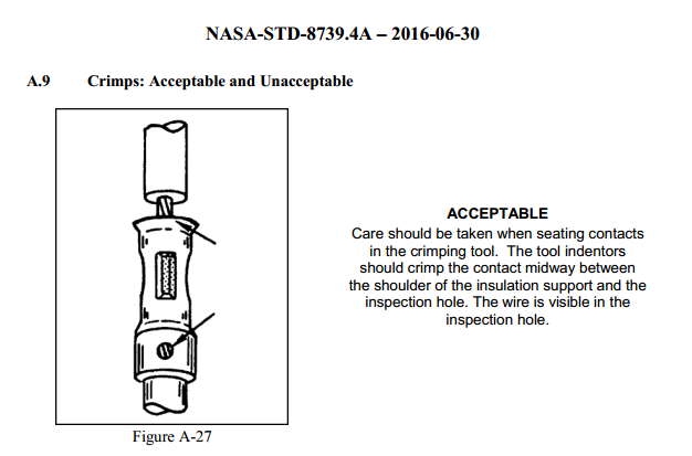
NASA doc on crimping is here: https://nepp.nasa.gov/files/27631/NSTD87394A.pdf
Page 97 has the following useful diagram on crimping these types of pins:

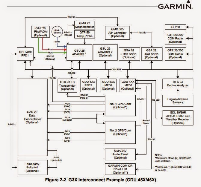
Source material for figuring out the wiring between the servos, magnetmeter and pitch trim motor.
Instructions for using the crimper (note that your's may not have the pre-adjustment described):

NASA doc on crimping is here: https://nepp.nasa.gov/files/27631/NSTD87394A.pdf
Page 97 has the following useful diagram on crimping these types of pins:
Source material for figuring out the wiring between the servos, magnetmeter and pitch trim motor.


My detailed diagram of the wiring. The numbers to the right of the components are the number of cores for the wiring for each group of signals on the left of the component.

High-level view showing the wiring.

Another view that's helpful to see the cabling from part to part.
