Subcribe to our RSS feeds Join Us on Facebook Follow us on Twitter Add to Circles

Categories

Tuesday, June 30, 2015

2 hrs. disassembling fuel tanks, pulling plastic and working on fuel sender floats.

Disassembled (it was only temporarily put together to test fit and ream holes) and plastic all pulled off.

Sender floats need to be cut to size and bent.  I had to reverse one of the rod to plastic ball connections since they will be mirror images.

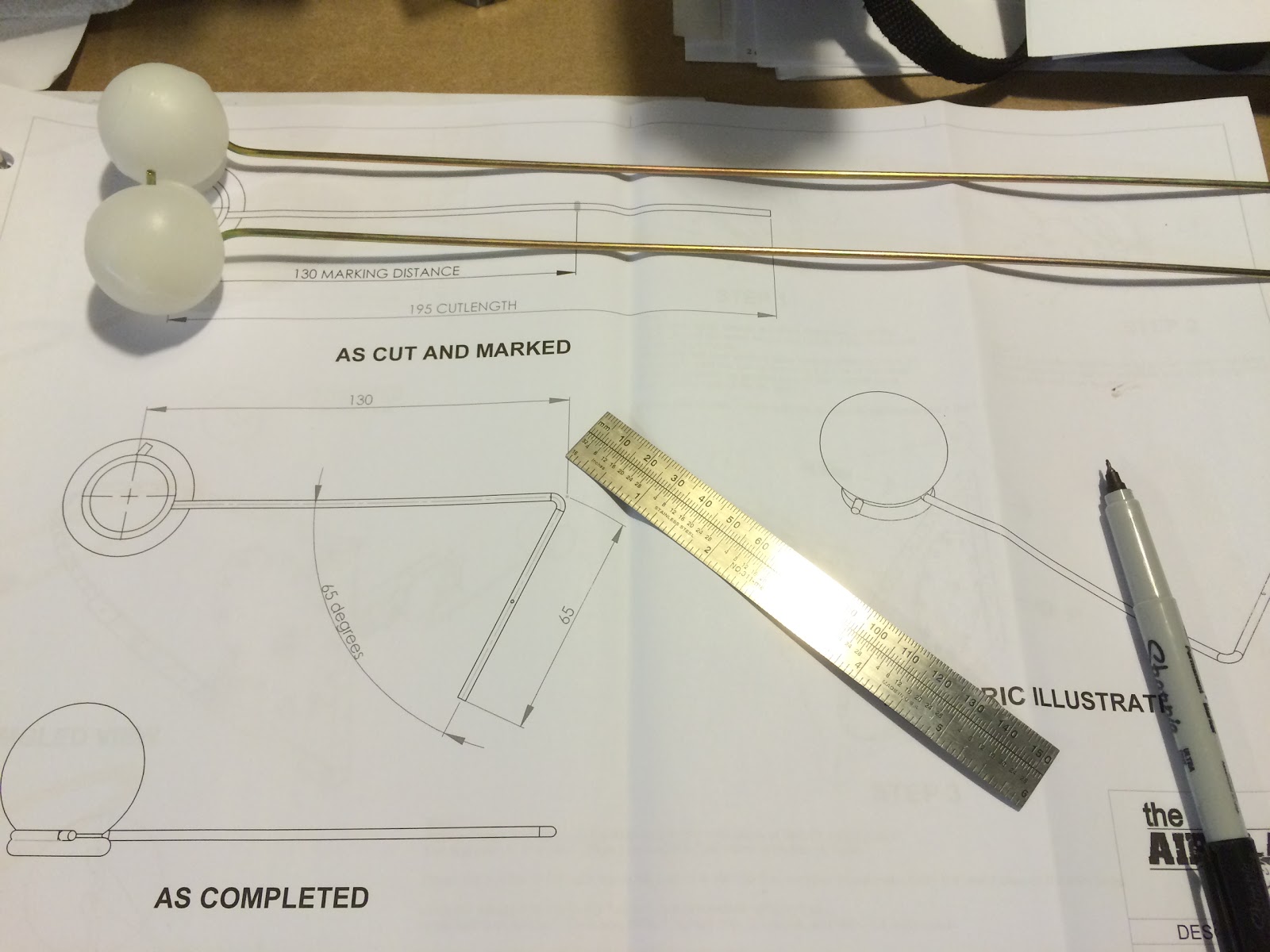
Measured out the cut and bend points.... But....

Use a ruler, the instructions are Not to Scale!

Starting the bend (still trying to figure out the best method of bending the rod - seems like it should be simple, but it's very stiff and it's the first time I'm doing it.).  Mostly using a vise, but I'm not convinced I'm doing it the best way to avoid a non-straight bend.

Sunday, June 28, 2015

2.5 hrs. reaming all the holes in the fuel tanks.

It was recommended to ream out all the holes to size before doing the Prosealing and riveting.  Doing that when it's got wet Proseal all ready to be riveted would have been a major mess.  Better to do it now!

Using my chucking reamer to ream the holes.

Monday, June 22, 2015

1 hr. yesterday working on the fuel sender.  It has to be reassembled with a part that comes with the kit.

Removed the original piece out of the sender (is that what it's called?).

Part from kit inserted and wire assembly temporarily connected to part.

Got my Proseal today!  Away for a few days and then when I return it'll be time to build the tanks!!   Was told by a fellow Sling builder about some good tips here.  Thanks Bob!

Friday, June 19, 2015

1.5 hrs. working on the fuel tanks.  Starting by cleco'ing the ribs into the skins.  Note that the fuel tanks will NOT be primed.  Just cleaned.

Put the skin in the jig.

A video showing how I cleco the ribs to the skins of the fuel tanks.  This is the last rib going on.  The first one is the hardest and you should be careful pushing down and aligning the rib so as to not buckle the rib.


Voila! :-)

I forgot to post this the other day.  I bought a high sensitivity torque wrench to measure the friction drag torque when I'm putting on nuts.  I have a click wrench for putting them on but you can't use that to measure the friction drag torque of the nuts before it's tightened.  You need to add that measured amount to the native torque value for the bolt you're using as your final torque value.

The way I measure the friction drag torque is to put the nut on the bolt down near where it will finally rest and turn it slowly with this torque wrench and see what it measures (I saw 5 in-lbs for the last one I tightened).  Then I add that amount to the native torque value from the torque chart for the AN bolts and that's my final total torque that I dial into my click-type torque wrench.

Here's Van's torquing instructions and torque chart for AN bolts.

Tuesday, June 16, 2015

1 hr. Starting prep of fuel tank parts.

Gordon has graciously lent me his fuel tank jigs.  Thanks Gordon!

 Plastic removed from most of the fuel tank parts (both sides).

This is the fuel sender as it comes out of the package (on the right).  The part on the left replaces the metal part inserted in the black plastic part.  See Gordon's below.

I visited Gordon last night (very helpful!) and he showed me what the fuel sender looks like after you replace the part shown above.

Sunday, June 14, 2015

1 hr. playing with Skin 1 on the bottom of the right wing and starting prep of the fuel tank parts.

As I mentioned in my last post the rivet lines on the main spar didn't seem to line up, so I un-cleco'ed all of skin 1 to see if I could get things lined up.  No Joy...  No matter how I slid it around there was no way the two rivet lines were going to line up.  This was the closest I could get them and it's clear something is wrong...  The skin holes are about 48mm on center.  The spar holes are close to 52mm on center.  4mm difference seems to me a bridge too far.  So, either the skin is wrong or the spar (hope not).

Zoomed out view to see where I was measuring.  Right bottom wing skin 1 near the root.

Saturday, June 13, 2015

2 hrs. Test fitting skins on bottom of right wing.

Checked for squareness of jigs and then checked the alignment of the ribs with the skin...  Not lined up on the main spar side!  Had to slide the main spar ends of the jigs to the right.  Notice how the skin holes don't line up with the rib underneath.

After sliding the main spar ends of the jigs - lined up! :-)

All cleco'ed up!  Looks good.

Well except for the end of the main spar near the root...  The holes don't quite line up.  If I un-cleco'ed the whole skin and re-cleco'ed starting from this end could I make up that distance and have everything still fit?  If anybody knows, please email me.

Friday, June 12, 2015

.5 hrs. drawing the top view of my latest paint scheme and flipping the wing (with a friend's help!).

This seems to fit with the side view I posted the other day.  Now I've got 2 years to figure out how to go from this to masks to paint an actual Sling 4.  Anybody know how?

A friend came over to help me flip the wing over so I can check the alignment of the rib bottoms and test fit the bottom skins. It was heavier than I thought it would be.  Should be interesting to put the finished wing up on the wall...  I'm thinking a padded jig to maneuver it around without damaging it.

Tuesday, June 9, 2015

1 hr. working on the nose ribs and other fiddling...

I was given a heads-up by builder Bob Zaleski that the forward-most flanges of the nose ribs should be rounded to better mate up with the leading edge skin.  Here's what it looks like before modification.

Using a socket and a rawhide mallet I rounded that flange (and the one on top).

And with a little additional filing, this is what it looks like.  Subtle curving.

Here's another nose rib where it's a little more visible.  Nice.

Page 8, Detail A says to check that the bottom of the rear spar meets up with the angle on the ribs.  Here's an example where it doesn't quite meet up.  For now I've cleco'ed them together, but I'll address this more thoroughly when I flip over the structure.

Miscellaneous  stuff that came in the mail!  Filler, for filling in the rivet heads (and fairing the various composite wing tips to the metal); Adel clamps of various sizes for electrical cabling, 14g wire for the pitot and nylon sheathing for the wiring.

Sunday, June 7, 2015

1 hr. fiddling with the wing and drawing a tweaked version of the last paint scheme I came up with.

So far, I'm liking this one the best of all.

Friday, June 5, 2015

Just a doodle today of a different idea for the paint scheme.


Thursday, June 4, 2015

1.5 hrs. Checking out my new ribs and their alignment with the rear spar and enlarging the holes for the step ribs.

I noticed the new ribs still stood a bit tall over the rear spar.  Then it occurred to me that maybe it wasn't the rib, but the rear spar flange angle.  Here's what it looked like after cleco'ing it in.

 I put a 4' ruler on the rear spar and there's a gap!  Meaning that the flange here is angled too low.

After some hand bending (and other spots on the spar that also had gaps), no gap!

And now it's way better lined up with the rib!  A little press (or bang) down on the rib and it should be perfect.

I ran the ruler all around the wing across all the ribs and at various points along the chord.  Very good alignment.  I'll do it again before I put the skins on again and when I'm closer to riveting.  Check, check and double check! :-)  We want the wing surface smooth.  If the underlying rib is a bit high or low, the skin will deform to meet it.

Starting to drill out the step rib holes to fit the 4.8mm x 15 rivets.  If you have later versions of the parts, you may not need to do this step.

Every surface needed deburring after using the chucking reamer (#11) to widen the holes.

All done!  Yay!

Tuesday, June 2, 2015

1.75 hr. riveting rear spar.  Decided it was better to take the rear spar off the jigs to rivet it since it was under some stress on the jigs and it was bending the connection between the two main sections.  I want it straight, so off it came.

First I found that the hinge part marked 5R was really 5L (and visa-versa), so I swapped the parts and the misaligned holes you see below went away.  This would have been easy to miss because all the holes you rivet at this stage were aligned.

The rear spar down in the ground and riveted!  All the holes I shouldn't rivet were marked with red dots (well except that first row which I knew shouldn't be riveted).

The other end.

Notice how the nose rib flanges are straight.  They need to be curved a bit so that the skin has a smooth curve and is not faceted.

Another builder suggested putting the autopilot controller at the top, so here's the updated panel drawing.