


Away for work for a few days. I'll be back at it on Friday when I'll re-check the right tank and finish more of the left tank.
Monday, November 30, 2015
Sunday, November 29, 2015
3 hrs. riveting the left tank.
I let it set slightly over the last 2 days and now it was ready to shoot the rivets. Remove every other cleco, dip the end of the rivet (the part that goes in) in just-made sealant and shoot it. After those are done, remove the remaining clecos and do those.

Spent 20+ minutes cleaning up the mess of sealant on the skin with MEK solvent....and it's done! And a first test fit of the fuel cap.

NEXT SESSIONS:
- Seal the fuel tank cap in place (some grinding down will be necessary to get a flush fit). Fuel drain is en-route (I ruined the one I had for this tank), so when that arrives that also must be sealed in place.
- Bend the drain tube and connect.
- Apply the more liquid sealant to all internal seams and rivet heads.
- Retest of right tank.
- Right wing down and start on the left wing!!
Saturday, November 28, 2015
Spent time today doing extensive updates to the, now renamed, Building and Testing Fuel Tanks page. Check it out!
Tomorrow morning I will rivet the entire left tank and perhaps get to the fuel cap fixture too.
Tomorrow morning I will rivet the entire left tank and perhaps get to the fuel cap fixture too.
Friday, November 27, 2015
5 hrs. working on sealing the leaks in the right tank and sealing the ribs and stringers in the left tank.
Hooked up my portable vacuum to "The Contraption" to get a suction in the tank. Tried to make it so that the suction from the vac was mostly pulling open air and some from the tank because you don't want much suction. Well, it still pulled too much (the skins were sucking in), so I opened up the other side of the contraption to allow more open air pulling and that seemed to work well. In this picture you can see the duct tape was closing up too much and so it was pulling too much from the tank. With the vacuum going I first brushed on MEK in all the leaking locations and then applied the more liquid version of the ProSeal to allow that to get sucked in. Released the suction and then cleaned up everywhere I applied the sealant. I'll give that 3 days to fully set and then test it again... Fingers crossed...

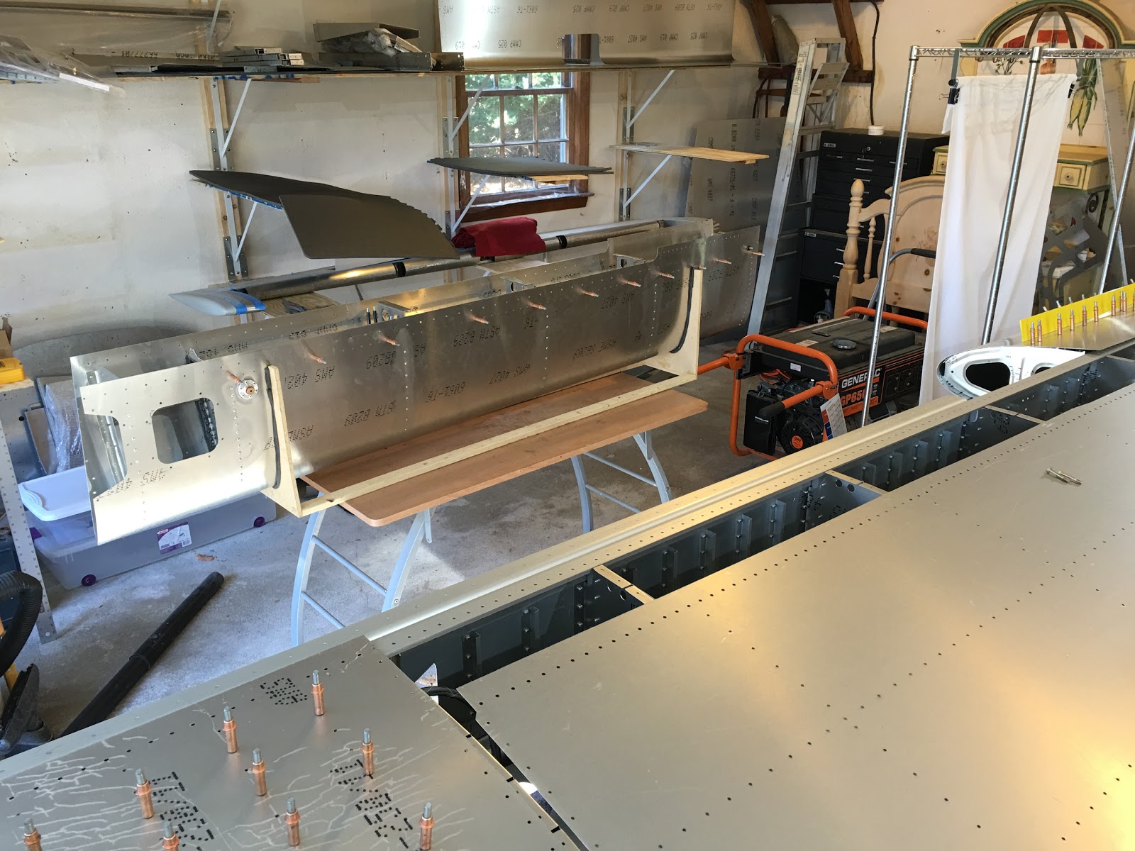
Getting ready to work on the left tank. End ribs of the tank are done first, then the stringer. Before this point I made sure rivets will go in all the holes - if not, then I reamed it out. After that I cleaned everything with MEK.

Here the end ribs and stringer are done. Every hole gets a cleco.

All the ribs are done! Let this semi-set overnight and then it will be riveted.

NEXT SESSIONS:
Hooked up my portable vacuum to "The Contraption" to get a suction in the tank. Tried to make it so that the suction from the vac was mostly pulling open air and some from the tank because you don't want much suction. Well, it still pulled too much (the skins were sucking in), so I opened up the other side of the contraption to allow more open air pulling and that seemed to work well. In this picture you can see the duct tape was closing up too much and so it was pulling too much from the tank. With the vacuum going I first brushed on MEK in all the leaking locations and then applied the more liquid version of the ProSeal to allow that to get sucked in. Released the suction and then cleaned up everywhere I applied the sealant. I'll give that 3 days to fully set and then test it again... Fingers crossed...

Getting ready to work on the left tank. End ribs of the tank are done first, then the stringer. Before this point I made sure rivets will go in all the holes - if not, then I reamed it out. After that I cleaned everything with MEK.

Here the end ribs and stringer are done. Every hole gets a cleco.

All the ribs are done! Let this semi-set overnight and then it will be riveted.

NEXT SESSIONS:
- Rivet the left tank.
- Seal the fuel tank cap in place. Fuel drain is en-route (I ruined the one I had for this tank), so when that arrives that also must be sealed in place.
- Bend the drain tube and connect.
- Apply the more liquid sealant to all internal seams and rivet heads.
- Retest of right tank.
- Right wing down and start on the left wing!!
Wednesday, November 25, 2015

Tuesday, November 24, 2015
1 hr. doing the final test of the wiring and tying it down.
Labeling all the wires (both ends of course). Here I'm using the tip position light sync wire as a ground so I can test that wire. Worked, so all the wires have been tested successfully for continuity.

I put all the ties through the holes and around the bundle before pulling any of them tight - otherwise it would have been more difficult to thread them around if the bundle was already pulled into the stringer.

And it's tied down. I'm wondering if where it goes from the step rib to the stringer needs further tying down. It's pretty stiff and hardly moves.

NEXT SESSIONS:
- Mix some of the less viscous sealant and work on the leaks I found.
- Start the sealing of the left tank.
- Though... I may want to put the right wing on its shelf and start working on the left wing before doing anything with the left tank... I really want to get started on the left wing!
Monday, November 23, 2015
Didn't work on it today, but wanted to relate what I found out about fixing fuel tank leaks.
You want to apply a slight vacuum to the tank for two approaches you can take (keep it slight!):
You want to apply a slight vacuum to the tank for two approaches you can take (keep it slight!):
- Apply Loctite 290 Self-Wicking thread lock and that usually fixes most leaks.
- Apply MEK, which cleans out the leak and then thinned ProSeal (or even better the less viscous variety I've mentioned before).
Sunday, November 22, 2015
1 hr (lots of home-related chores taking up a lot of time these days...) testing the fuel tank - and more successfully this time!
Deflategate! This first attempt was a clear failure...

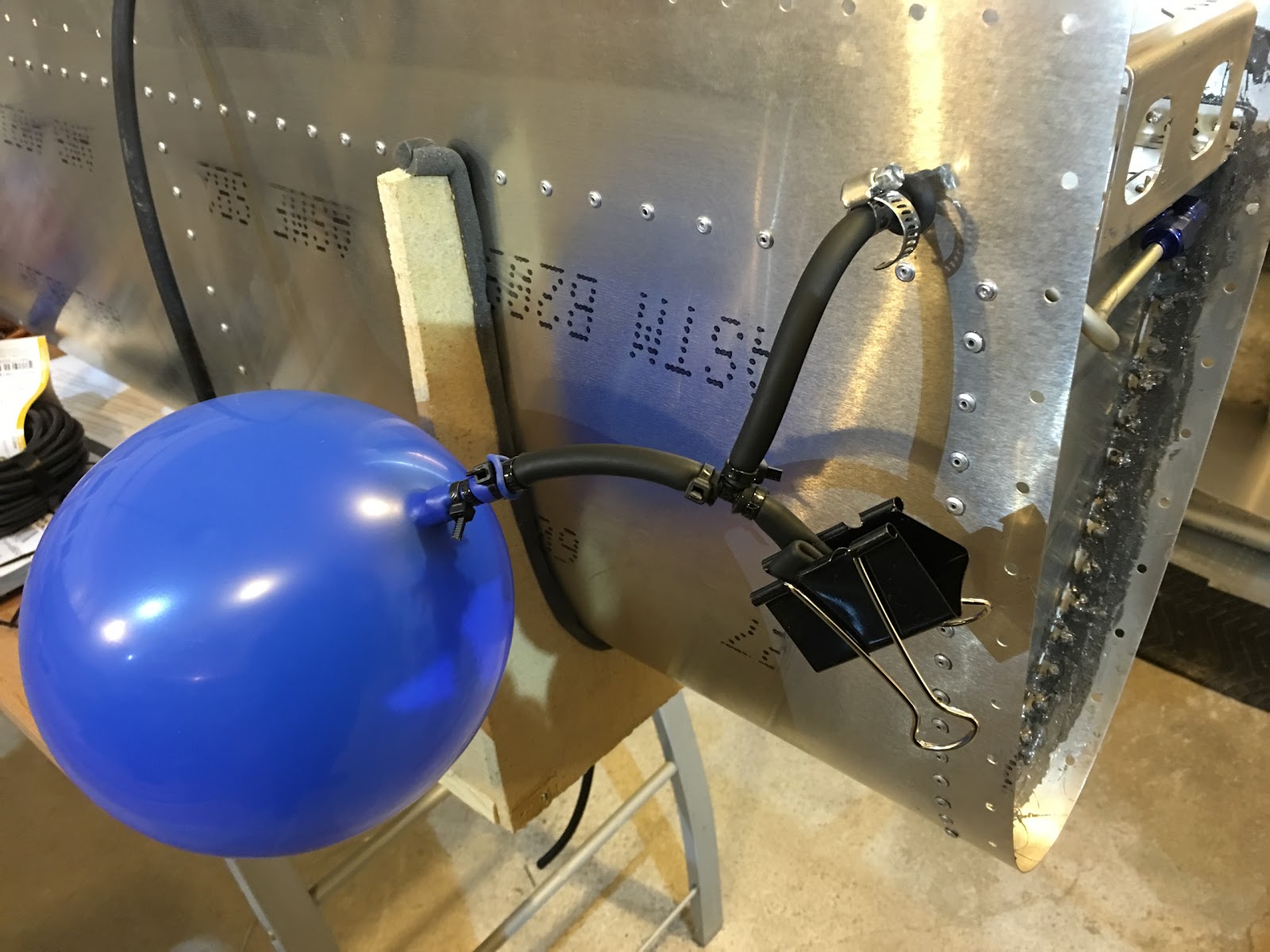
I put another balloon on and put just 3 tie-wraps around it because I thought it was leaking around there with all the tie-wraps I had put there in the first attempt. As soon as I blew this one up nice and big I could hear a slight hiss - but it wasn't coming from "The Contraption"! It was coming from the other side of the tank, so I started hunting...

Found the rivet that seemed to be making the sound and put my finger on the head and it stopped! So, I put some painter's tape over it and the balloon seemed to be staying inflated. So, next I whipped up some dish soap and water and started painting with a brush. Here's some of the "painting." No leaking with those rivets.

Brush on some soapy water over the one I found leaking and this is what you get.

Found one more leaky rivet on the other side.

After finishing with all the rivets, I started all the seams and found one spot that was leaking. See the video below for that one in action!

Also soaped up the fixtures and found one spot that was leaking around the fuel return fixture in the upper left which is just out of frame in this picture. The trick is you have to brush the soap on and watch it for multiplying bubbles.

Here's the first leaking rivet I found:
Deflategate! This first attempt was a clear failure...

I put another balloon on and put just 3 tie-wraps around it because I thought it was leaking around there with all the tie-wraps I had put there in the first attempt. As soon as I blew this one up nice and big I could hear a slight hiss - but it wasn't coming from "The Contraption"! It was coming from the other side of the tank, so I started hunting...

Found the rivet that seemed to be making the sound and put my finger on the head and it stopped! So, I put some painter's tape over it and the balloon seemed to be staying inflated. So, next I whipped up some dish soap and water and started painting with a brush. Here's some of the "painting." No leaking with those rivets.

Brush on some soapy water over the one I found leaking and this is what you get.

Found one more leaky rivet on the other side.

After finishing with all the rivets, I started all the seams and found one spot that was leaking. See the video below for that one in action!

Also soaped up the fixtures and found one spot that was leaking around the fuel return fixture in the upper left which is just out of frame in this picture. The trick is you have to brush the soap on and watch it for multiplying bubbles.

Here's the first leaking rivet I found:
Here's the leaking seam I found:
On an unrelated note, I was told in the builder's forum about a fuel injection kit for the Rotax 914 from a Norwegian company, EdgePerformance, that looks great. Much better than the throttle body injection I was looking into. Here are two docs which talk about the product:
I was also told about a big bore kit that might be interesting (I need to read more about this):
I can definitely get excited about more power, better fuel efficiency and no carb heat required!
NEXT SESSIONS:
- I've decided to put off working on the left fuel tank until the right is leak-free. So, I need to whip up some sealant and work on the leaks I found.
- Test the strobe sync wire to the tip (use it as a ground temporarily), so then I'll have tested all the wires in the bundle.
- Tie down the wire bundle.
- Once all the above is done, then start the sealing of the left tank.
- Though... I may want to put the right wing on its shelf and start working on the left wing before doing anything with the left tank... I really want to get started on the left wing!
Friday, November 20, 2015
1.5 hrs putting together the fuel tank test contraption.. and test fit of the left tank ribs.
Got my 1/4" inner diameter rubber tubing. That's too soft to tie a balloon to, so I inserted a harder plastic tube in that to wrap the balloon around.

Here's the whole contraption...

Blew it up with the right end, which pressurizes the tank and then blows up the balloon... The clip on the right seems leaky so I'm guessing it will not hold the air overnight. What I don't want to do is debug leaks of my contraption, when the goal is to test the tank. If I can't quickly resolve the contraption air loss issue I will just pressurize the tank and do the soapy water test on all the rivets and fixtures (which I'll do in any case).

Taped over the fill cap and...

...drain.

Cleco'ed together the left tank! Hoping to do the sealing (oh joy!!) of that on Sunday.

Got my 1/4" inner diameter rubber tubing. That's too soft to tie a balloon to, so I inserted a harder plastic tube in that to wrap the balloon around.

Here's the whole contraption...

Blew it up with the right end, which pressurizes the tank and then blows up the balloon... The clip on the right seems leaky so I'm guessing it will not hold the air overnight. What I don't want to do is debug leaks of my contraption, when the goal is to test the tank. If I can't quickly resolve the contraption air loss issue I will just pressurize the tank and do the soapy water test on all the rivets and fixtures (which I'll do in any case).
Taped over the fill cap and...

...drain.

Cleco'ed together the left tank! Hoping to do the sealing (oh joy!!) of that on Sunday.

NEXT SESSION:
- See if the contraption is working (probably not). If not and I can't quickly fix that, it's time for Plan B.
- Sealant for all the ribs and stringers of the left tank.
Wednesday, November 18, 2015
1 hr. continuing the wiring work.
Did get the end caps for the tank testing, but not the tubing yet. We'll see how sealed these caps are when I pressurize the tank (just with a balloon!).
The two sizes needed are 4 and 6, which you can get here.

Wired up the outer landing light and it works! I confirmed that putting in the two loose plates with the screw and compression spring is a exercise in super-human dexterity. I actually couldn't do it for the outer light's left side screws. I'll either have to get an right-angled pliers or figure out how to make the whole light sub-assembly structure more put together before attempting to connect it the wing.

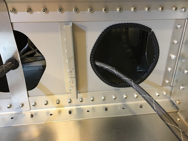
Put some edge grommet around the hole where the wire bundle re-enters.
Wired up the wing tip strobe/position light!
NEXT SESSIONS:
Did get the end caps for the tank testing, but not the tubing yet. We'll see how sealed these caps are when I pressurize the tank (just with a balloon!).
The two sizes needed are 4 and 6, which you can get here.

Wired up the outer landing light and it works! I confirmed that putting in the two loose plates with the screw and compression spring is a exercise in super-human dexterity. I actually couldn't do it for the outer light's left side screws. I'll either have to get an right-angled pliers or figure out how to make the whole light sub-assembly structure more put together before attempting to connect it the wing.

Put some edge grommet around the hole where the wire bundle re-enters.

Wired up the wing tip strobe/position light!
NEXT SESSIONS:
- Test right tank.
- Work on the left tank.
Tuesday, November 17, 2015
1.5 hrs. separating out the landing light wiring from the bundle and wiring up a light.
I posted a question in the Engine topic of the builder's forum, so please check it out.
The two landing light 2-core wires separated out from the bundle heading to the wing tip nav/position light.

And it's routed through.

Wired up and connected to a battery at the fuselage end of the wire bundle and it lights!! After this I labeled all the landing light wires.

NEXT SESSIONS:
- Wire up the other landing light and test.
- Tubing to connect to the fuel vent is arriving tomorrow and end caps might be arriving tomorrow, so as soon as I have all that I'll be able to test the tank.
- I got more cleco's (I was running short) recently, so I can work on the left fuel tank. I'd like to have that done (well, as far as I can have it done without the wing to connect to) by this weekend.
- Wire up the wing tip nav/position light and test.

Monday, November 16, 2015
I created a system function table showing what the primaries and backups will be. I put this table in the Avionics & Electrical page, but at the moment that page's formatting is all screwed up. :-(
Thoughts?
| Function | Primary | 1st Backup | 2nd Backup |
|---|---|---|---|
| Airspeed/Altitude/VS | G3X | GRT MiniEFIS | iPad Pro (GPS-Based) |
| Attitude/SynVis | G3X | GRT MiniEFIS | iPad Pro (Distinct HW/SW for all 3!) |
| VFR Nav | G3X | GTN650 | iPad Pro (3rd Backup: iPhone) |
| IFR Nav | GTN650 | G3X | iPad Pro |
| Weather(ADS-B) | iPad Pro (Separate ADS-B In) | G3X | GTN650 |
| Traffic (ADS-B) | G3X | GTN650 | iPad Pro (Separate ADS-B In) |
| Terrain/Obstructions | G3X | GTN650 (?) | iPad Pro |
| Engine Monitor | G3X | -none- | -none- |
| Comms | GTN650 | G3X (2nd Comm) | Handheld |
Sunday, November 15, 2015
1 hr. working on the landing lights for the right wing. Also mocked up using an iPad Pro for the second screen.
M4 Rivnuts installed (after I enlarged the holes to accommodate them). Loctite 277 was used as per the instructions.

Using the M4 x 22mm buttonhead screws and compression springs one of the landing lights is installed!

Close-up showing the compression spring. Maybe use a sleeve to prevent the squeezing between the front and rear plates? Does it matter?

Panel mocked up with the iPad Pro on the right side instead of a 2nd G3X screen. I think this is actually more fault tolerant than 2 screen G3X screens due to the system software diversity. It's not shown here, but Foreflight can have synthetic vision so my panel would have 3 different SynVis displays with completely different software: Garmin, GRT (Grand Rapids Tech) in the middle (which will also have air data) and Foreflight on the right. Having the Pro on the panel will be Amazing because of it's large and gorgeous display.

NEXT SESSION:
- Remove wing skin to give me access to the wiring so I can wire up the landing lights and test them out.
- Waiting on some end caps before I can test the fuel tank.
Friday, November 13, 2015
1 hr. trimming down the bottom side edge of the fuel tank. Also continued contemplation of how exactly to test the tank...
Straightedge lined up (5mm below the cut line). Lots of clamps because I do not want that guide to move...

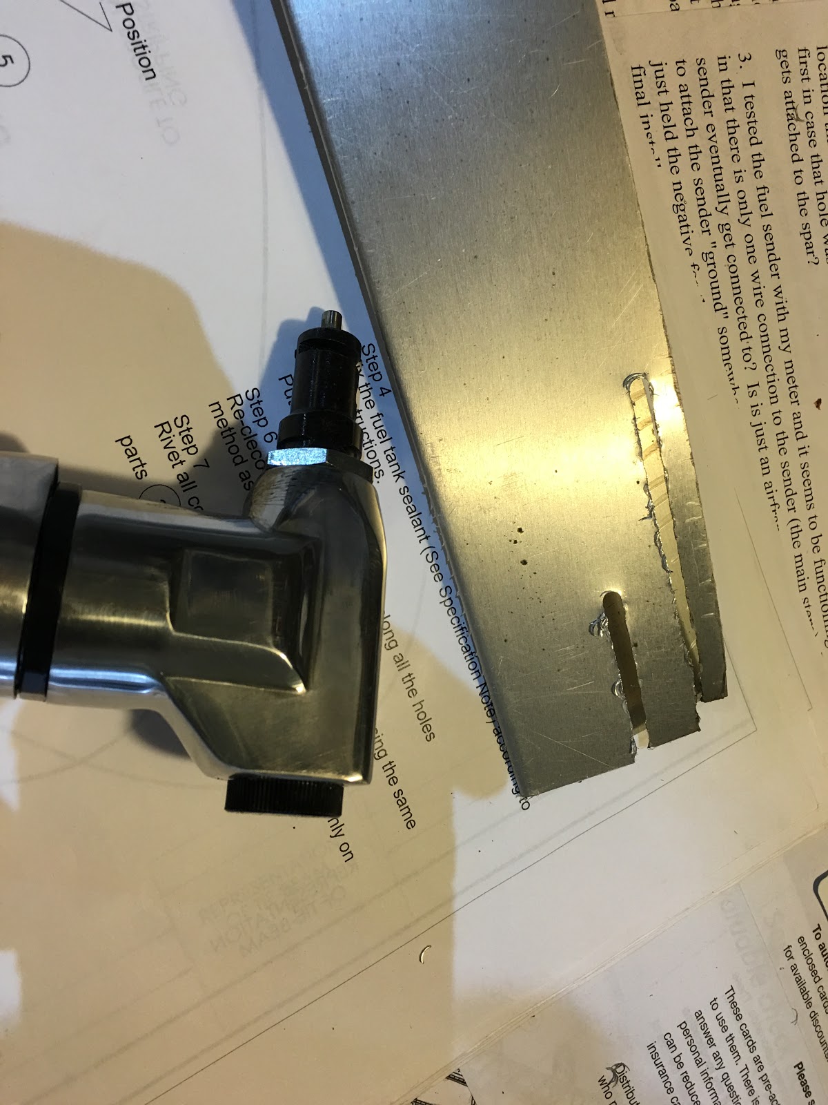
As I cut I move the clamps out of the way and put it behind the cut (far enough to be able to put the nibbler in straight).

And it done! Filed and deburred for a straight and clean line.

NEXT SESSION:
Straightedge lined up (5mm below the cut line). Lots of clamps because I do not want that guide to move...

As I cut I move the clamps out of the way and put it behind the cut (far enough to be able to put the nibbler in straight).

And it done! Filed and deburred for a straight and clean line.

NEXT SESSION:
- Further contemplation on testing the tank...
- But, if it turns out I need to buy things to do that, I will move onto the next thing I can do to not lose time. Perhaps putting in the M4 Rivnuts for the landing light mount.
Wednesday, November 11, 2015
2 hrs. taking the now sealed fuel tank off the wing and trimming back the skin on the top.
Before I get into the pictures I'd like to encourage people to join the builder's forum I added to the site. I know it might take a while to get busier, but that will only happen if people join and post. So please do! Thanks! Now, back to our regular programming... ;-)
Following Gordon's advice to put painter's tape on the spar so the fuel tank wouldn't stick was a good move. As you can see here it would have been very frustrating if it had stuck. Even with this there was still some stickiness and I had to give it a good tug to get it off.

And it's off! Contemplating how to do the leak testing. There are two openings on this end and the drain at the other end. I'm thinking to plug these two and attach a balloon to the fuel drain with a tee connection to enable blowing it up (basically stealing Gordon's idea ;-)). Thanks Gordon!

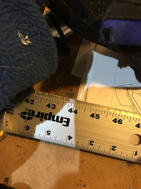
While I contemplate (and obtain the necessary fixtures) it's time to trim back the skin where it didn't line up with the leading edge. The two dashes at the left end are: top line, where I want the cut (8mm from top edge) and the bottom line (5mm away from that) where the straightedge will go and the nibbler will ride along.

Ready to go!

Here's a video of me doing the cut:
Perfect!

NEXT SESSIONS:
Before I get into the pictures I'd like to encourage people to join the builder's forum I added to the site. I know it might take a while to get busier, but that will only happen if people join and post. So please do! Thanks! Now, back to our regular programming... ;-)
Following Gordon's advice to put painter's tape on the spar so the fuel tank wouldn't stick was a good move. As you can see here it would have been very frustrating if it had stuck. Even with this there was still some stickiness and I had to give it a good tug to get it off.

And it's off! Contemplating how to do the leak testing. There are two openings on this end and the drain at the other end. I'm thinking to plug these two and attach a balloon to the fuel drain with a tee connection to enable blowing it up (basically stealing Gordon's idea ;-)). Thanks Gordon!

While I contemplate (and obtain the necessary fixtures) it's time to trim back the skin where it didn't line up with the leading edge. The two dashes at the left end are: top line, where I want the cut (8mm from top edge) and the bottom line (5mm away from that) where the straightedge will go and the nibbler will ride along.

Ready to go!

Here's a video of me doing the cut:
Perfect!

NEXT SESSIONS:
- Cut bottom edge back to match.
- Get together the necessary fixtures to do the leak test and...
- Test!
Monday, November 9, 2015
1 hr. testing out the nibbler and then using it to enlarge the holes for the landing lights.
Clamped down a straightedge on my test material and ran the nibbler along it. Turns out the distance from the straightedge to the cut is exactly 5mm. Note the crescent-shaped shards on my sleeve.
After removing the plastic film and deburring the edge it looks pretty darn perfect.

My test of cutting along a curve on this trashed landing light plate (from a previous failed experiment with a jig saw...). Test is to remove the material to the line.

And it works pretty well. Not perfect, but good enough for this task.

This is how I used the nibbler - gently running along the edge. If you push, it will go right through the material...

And the final result (I also ran a Dremel with a Scotchbrite wheel along the edge to smooth it)- not perfect, but good enough. There's probably a better way to have done this, but I don't have that tool...
Now I need the 25mm buttonhead screws that are missing from my kit...

Holding a 4' straightedge along the leading edge shows a slight gap in the area of the landing lights. Problem?

NEXT SESSION:
Clamped down a straightedge on my test material and ran the nibbler along it. Turns out the distance from the straightedge to the cut is exactly 5mm. Note the crescent-shaped shards on my sleeve.

After removing the plastic film and deburring the edge it looks pretty darn perfect.

My test of cutting along a curve on this trashed landing light plate (from a previous failed experiment with a jig saw...). Test is to remove the material to the line.

And it works pretty well. Not perfect, but good enough for this task.


And the final result (I also ran a Dremel with a Scotchbrite wheel along the edge to smooth it)- not perfect, but good enough. There's probably a better way to have done this, but I don't have that tool...
Now I need the 25mm buttonhead screws that are missing from my kit...

Holding a 4' straightedge along the leading edge shows a slight gap in the area of the landing lights. Problem?

NEXT SESSION:
- Need to wait until Wednesday to remove the tank and test for seal.
Sunday, November 8, 2015
6 hrs. sealing the right fuel tank! And other miscellaneous things.
I've spent several hours over the last week finishing up the new shelving. For the smaller fuselage skins I put them in a large plastic bin.

All the fuselage parts are out of the box and on the shelves! I put them so that I can see the package labeling. Lots of parts, so I want to be able to find things reasonably quickly.

I bought this back when I was first ordering tools and I have no idea what it is! Thoughts?

Close up. Seems to have two functions. I think the one of the right side makes can create a jog in sheet metal. The left side?

Testing out my new nibbler. Works well! With a clamped-down straight edge I should be able to get a very nice straight cut. Will use it for trimming the fuel tank and enlarging the holes for the landing lights I use (PAR-36 standard lights). That may be what I do tomorrow.

Fuel tank off!

I marked all the z-brackets so that when I'm ready to put them on with sealant I wont have to re-figure out how they're oriented.

Taped up so that no sealant will get on the wings when I hang the tank.

All the z-brackets sealed and riveted on with sealed rivets (except the end ribs which do not require sealed rivets). Also the back channel has the sealant applied where it contacts the fuel tank skin.

And that's it! The tank is, at least theoretically, sealed! It needs to hang on the wing, per the instructions, for 3 days, to set up the sealant.

NEXT SESSION:
I've spent several hours over the last week finishing up the new shelving. For the smaller fuselage skins I put them in a large plastic bin.

All the fuselage parts are out of the box and on the shelves! I put them so that I can see the package labeling. Lots of parts, so I want to be able to find things reasonably quickly.

I bought this back when I was first ordering tools and I have no idea what it is! Thoughts?

Close up. Seems to have two functions. I think the one of the right side makes can create a jog in sheet metal. The left side?

Testing out my new nibbler. Works well! With a clamped-down straight edge I should be able to get a very nice straight cut. Will use it for trimming the fuel tank and enlarging the holes for the landing lights I use (PAR-36 standard lights). That may be what I do tomorrow.
Fuel tank off!
I marked all the z-brackets so that when I'm ready to put them on with sealant I wont have to re-figure out how they're oriented.

Taped up so that no sealant will get on the wings when I hang the tank.

All the z-brackets sealed and riveted on with sealed rivets (except the end ribs which do not require sealed rivets). Also the back channel has the sealant applied where it contacts the fuel tank skin.

And that's it! The tank is, at least theoretically, sealed! It needs to hang on the wing, per the instructions, for 3 days, to set up the sealant.

NEXT SESSION:
- Do some test trimming with nibbler along straight edge.
- Do some test trimming with nibbler for landing light plates.
Subscribe to:
Posts (Atom)