Subcribe to our RSS feeds Join Us on Facebook Follow us on Twitter Add to Circles

Categories

Friday, August 31, 2018

3.5 hrs. mostly on the main wheels.

EDIT (9/8/2018): I found that when I put the finished spats on the wheel they had to bend around the wheel brackets which made a few of the holes added below not line up properly with the underlying rivnuts.  I suggest just doing the bottom two holes on each side of the spat cover and waiting until it's on the wheel to see where those holes should be drilled.  You can put all the rivnuts in now though.

OK, this is funny.  I forgot that I left out the mineral spirits from the other day...  Seeped through a bit, but didn't spill. :-D

I forgot to put in washers for the screws on the nose wheel.  It shows washers for the screws that connect the spat to the wheel, but doesn't show any (or mention) washers for the screws that connect the halves.  I'll assume I need to add those too.

I figured out the wobble of the left wheel (this is the right)...  I hadn't tightened all the bolts on that wheel... Duh...  So, I had to remove it from the axle and remove the disk to tighten all the bolts.  Now it spins perfectly.  Whew...  Patience is a virtue when building an airplane...

Time to work on the main wheel spats.  We need to attach the cover to the spat.

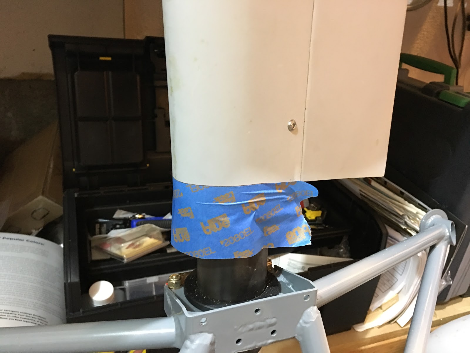
Clamped down for best fit.

...And taped.

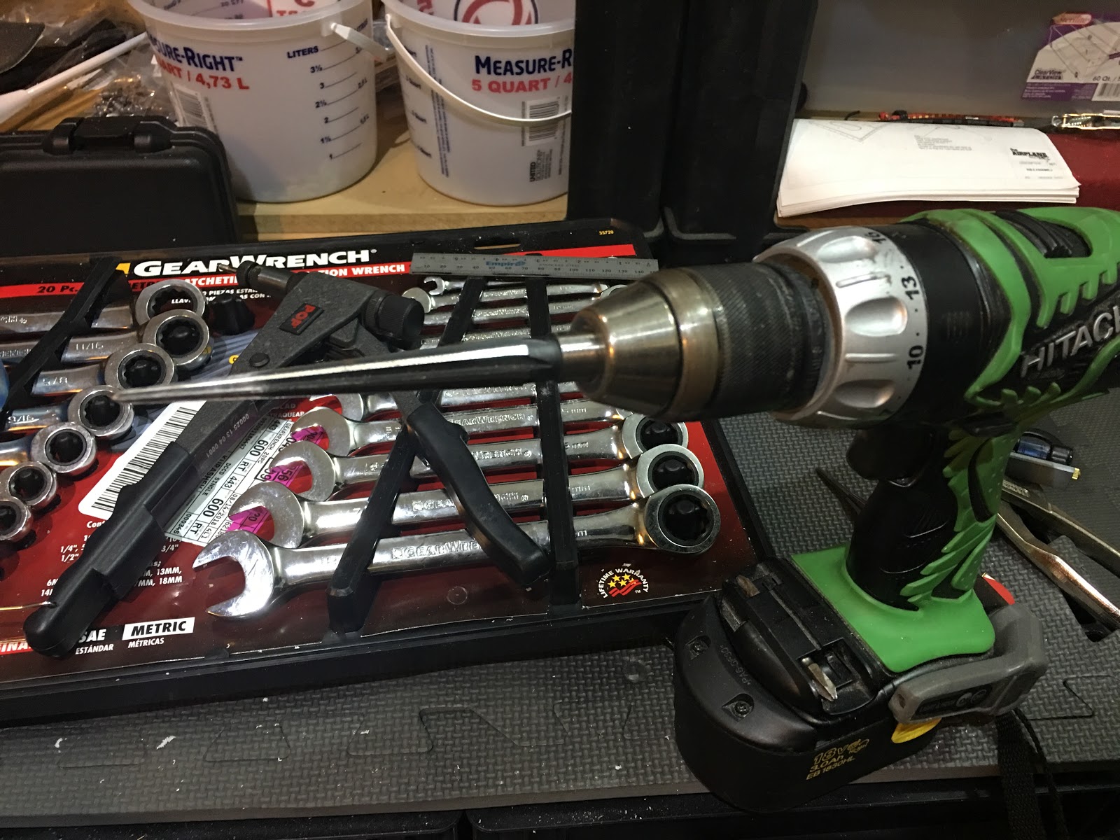
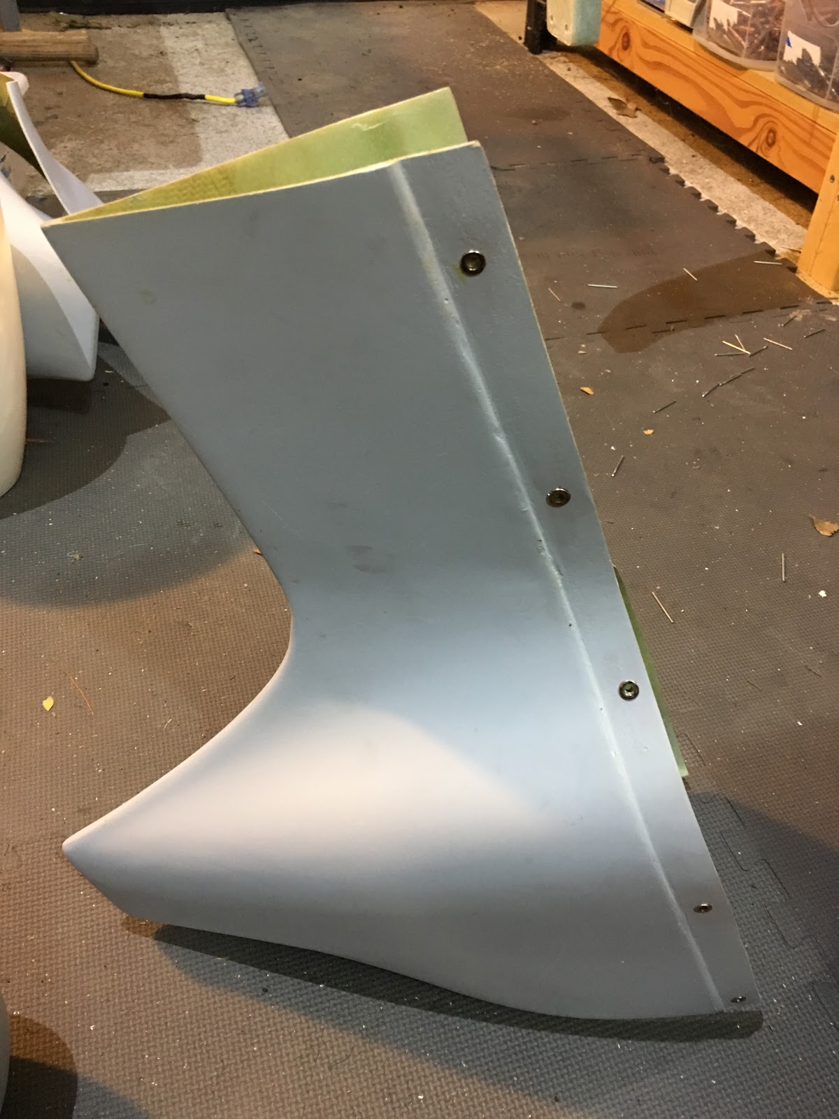
Pilot holes drilled.  Remember to drill in straight, otherwise the holes in the two pieces will be slightly off and we don't want that.

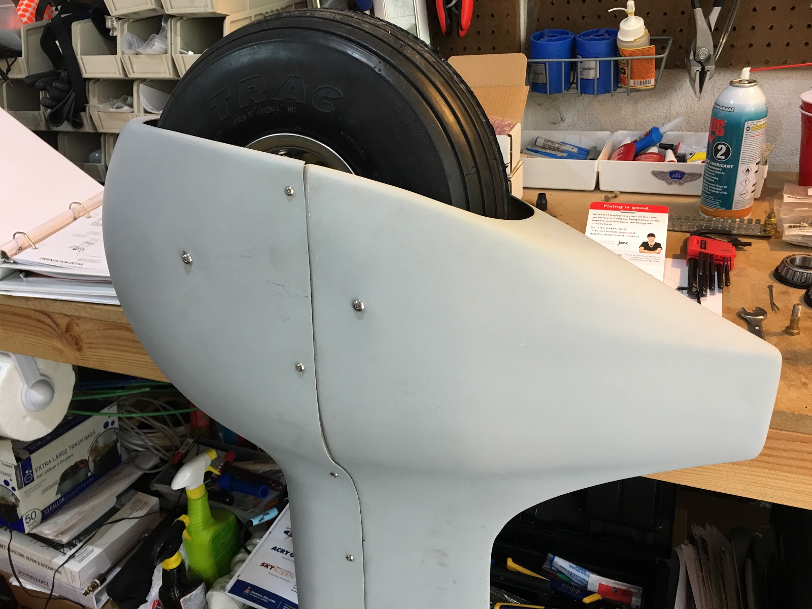
Enlarging the holes and adding cleco's as I go to ensure alignment.

Used my drill-driven manual reamer to carefully enlarge the inside hole to accommodate the M4 rivnuts.  I had already enlarged the outer holes to accommodate the M4 screws.

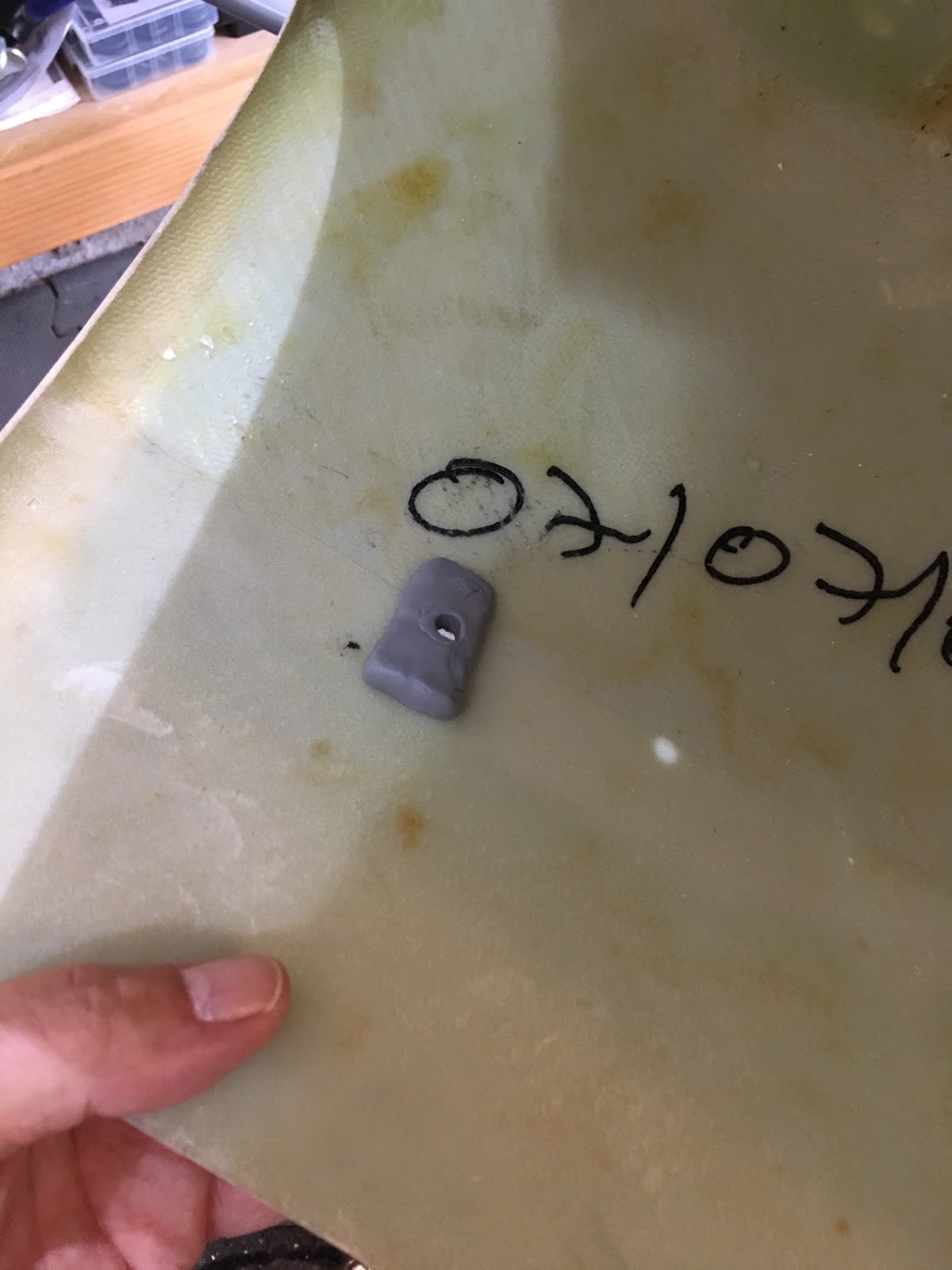
Don't over-pull the rivnuts.  No more than this.

And it's done!  Tomorrow I'll do the other one and start the process of attaching them to the wheels.

Wednesday, August 29, 2018

1.5 hrs. on the main wheels.

Getting ready to clean and rinse the bearings with mineral spirits and isopropyl alcohol.

After reviewing an EAA video on packing wheel bearings, this is probably too much...  But, not all of it went in anyway...

Bearings packed.  After this photo I wiped down the inside surfaces as they shouldn't have much grease on them.

You need to be careful when you put the bearings in since the rubber seal gets easily caught and is easy to miss unless you're looking for it.  In this picture it's fine.  And, oh, I almost forgot that the disk brake had to be attached here before putting it on the axle (the manual shows the disk, but doesn't mention it).

Both sides on (though not the difficult to insert split pins).  This side though seems to have a very slight wobble, which I assume is not good...  Haven't fully investigated what's causing that.  Anybody seen that?  Thoughts?
After 90 minutes in the 90 F degree (32.2 C) heat, I was dripping and had enough...

Tuesday, August 28, 2018

1 hr. putting in the tire valve access hole and grommet.

I was told by the factory that they enlarged the nose wheel access hole to be the same as the main wheels to make it easier to access.  So, the hole location and dimensions in the manual are not correct.  The hole needs to be 45mm across.  I decided to eyeball where it should go...

...based on being clear of things on the other side and....

...lining up with the valve.

45mm diameter traced out.  I started with drill bits, then I went to my step drill to get it bigger, but not too close to the line as they don't make smooth holes (and my step drill bit isn't that big anyway).  I wore a mask for the whole process...  Don't Breathe Fiberglass....

I took it to the line with this Dremel sanding/grinding bit.

That works!

Took 5 minutes of witchcraft to get that grommet in.... :-O

Monday, August 27, 2018

1.5 hr. on the nose wheel.

Looks like my wedge of Sugru worked very well.  It sticks to the fiberglass and it seems to be just the right thickness.  Also, I switched the other two M5 buttonhead screws to be x20's.  The x12's are not long enough IMHO.

Time to trim off that extra piece of fiberglass.

This saw worked well.  Quick work.  Probably over-cautious, but I wore gloves and a mask for this...  Not a fan of breathing fiberglass dust or getting it on my hands which I discovered can take days to wash away (and can be painful).  After sawing it off I filed it to make it nice and even all the way around.

Nice!
Hmm...  The manual shows the hole needed for this grommet is 29mm (am I reading it right?), but the inner diameter is 40mm (goes from the 10mm to 50mm marks).  What am I missing?


I'll check other blogs, but is this right?  The engine mount bolts face backwards?  Oh, and it calls for AN5-5A bolts for 2 of the holes....  and I don't have that size...  Grr....  Back to Aircraft Spruce.... :-/
EDIT: I see that JimP used -6A's for those holes.  I did order -6A's too.  He also put the bolts the way the FAA recommends.  Wonder why the manual shows the other way?

I was looking through the maintenance manual last night when I noticed that it had a diagram showing the main gear bolts which connect it to the fuselage as having the nuts forward and the bolt heads toward the rear.  Since the construction manual does not have this indicated I installed them how the FAA recommends, head forward and the nuts toward the rear.

I checked in with the factory (Mike) and my installation is fine.  The only reason they show it the other way in the maintenance manual is because of the preference of the workers in the factory in SA.  I didn't have any issue putting it in as the FAA recommends.

Even if all those nuts came off....  Those bolts would not come out...  They are in very tight...

Saturday, August 25, 2018

3.5 hrs. on the landing gear.  Also had a visit from my local EAA chapter 196.  I should have taken a picture!  Showed them the plane and they graciously helped move the plane back a couple of feet so I can install the engine mount without interfering with the garage door.  Thanks!

Here you can see some light coming through the dimple of the nose wheel spat.  You can see it's a bit off from the rivnut, so I will drill through where it's lined up.  Using a very small drill bit I can incrementally enlarge it so that it's perfectly lined up.

First small hole drilled and this is better lined up.

 I kept enlarging it and checking where I was in relation to the rivnut.  Worked perfectly.

The manual says M5x12 for the 4 holes, but this one (and the other side) it's better to use x20's to span that gap.

All done with the drilling.

Molding the sugru I mentioned in the last post to span that gap (I measured the gap to see how thick to make it.  And it's not a constant thickness as it tapers down).  I need to let this dry overnight and see how it'll work.  I'm not certain it'll stick to the fiberglass so I may need to glue it.

While that's drying I worked on the main wheel assemblies.  I got the AN4-22A bolts from Aircraft Spruce, so I swapped them in and those fit as expected.  Here they're in and torqued properly.

Hmm..  The right side all lined up, but the left side had one bolt that didn't line up.  I trimmed the spat bracket hole to allow the bolt to pass through.

 Half of the brake assembly tapped into place.

And the other side too.

Thursday, August 23, 2018

1.5 hrs. on the nose wheel.

Widening those holes with the manual reamer was tediously slow...  Hey, no one said I couldn't put the manual reamer in a drill. :-)  Worked like a champ.   Still accurate, but MUCH faster.  Just make sure not to go too far.

It's a beautiful thing. ;-)  I'll trim off that long top later.

The four holes for attaching the spat to the gear are dimpled.  This one looked fine, but the next one didn't, so I measured this one against the other one.  This is about 112mm from the edge.

To the center of the misshapen hole is about 114mm, so I don't think this side is right.  Before I drill anything, let's see how it fits and scope things out.

Here's the fit.

I marked off 112mm, but I don't want to drill those front holes yet.

Maybe hard to see here, but there's a gap between the rivnut and the front spat.  You can actually see photos of Slings where the spat is pulled in.  We don't want that, so I'm going to do what Bob Zaleski recommended and use Sugru, a moldable glue to span that gap.  I already have that material on hand.

I drilled the two back holes that had more precise dimples and put in the M5 buttonhead screws.  With those located I can be more confident in locating the front holes properly.  To be done either tomorrow or Saturday.

Wednesday, August 22, 2018

2 hrs. last night and this morning on the nose wheel spats.

Taping and clamping the spat halves together.  Excellent fit.

Starting to drill out and cleco the holes (there are slight dimples where they should go).

One side all done.

Saw a tip from Jean (via Jim) to use the hand reamer to enlarge the holes to fit the M4 rivnuts.  I agree with this approach as it results in a more precise location vs. a chucking reamer in a drill.

Since the material is soft vs. aluminum, don't over-pull the rivnuts.  Also make sure they're going in straight as you pull, as it's easy for it to be pulled at an angle.

One side done.  I'll finish tonight.