Subcribe to our RSS feeds Join Us on Facebook Follow us on Twitter Add to Circles

Categories

Monday, December 31, 2018

2 hrs. on rear interior skins.

First, Happy New Year 2019!  Hard to believe it's 2019 - that sounds like the future! 😁

Needed to cut out a notch for the passage of the seat belt.  I think newer skins have this notch already (?), but mine didn't.

This area needed to be opened up to allow for access to the lower seat belt attachment.

Getting there!  Should finish this tomorrow and start on the other side.

In other news, I've removed my fuel tanks build page as other Sling builders have better methodology, so please seek them out for assistance.

Saturday, December 29, 2018

3 hrs. misc.

Spent a chunk of that time talking to Steve from Aircraft Specialty discussing my brake lines because I still had a question as to a particular fitting.  After talking to him I may revamp it so that it's SS braid all the way to the reservoir.  If it's all the same it makes it much simpler.  Stay tuned.

No photos today as I just made the new wire bundle for my right seat and routed that through.  Other than that I also removed the current brake line Tee in anticipation of re-doing it.

I've been going through my set of Tony Bingelis books (he was the dean of aircraft home-building for decades) and came across this good tidbit.  I'll do this for all my non-insulated terminal connections for sure.  I was planning to do the heat shrink, but hadn't considered the soldering part.

Wednesday, December 26, 2018

I spoke to Steve (the owner) at Aircraft Specialty (highly recommended!), the company that made my SS brake lines and he was super helpful in explaining the tightening and sealing (or not) of the various fittings in my brake system.  He also simplified my brake system a bit by taking out the coupling (he did recommend going all SS braid, but I'll stick to the plastic tubing up to the hand brake for now).  I'll post an annotated picture of the updated arrangement once I get back to that in a few days (some parts on order).

He sent this guide to tightening the flared type fittings on the end of their hoses (no thread sealant of any sort on these types of connections!).

For the Tapered NPT connections like the threads of the Matco calipers a local friend sent this (the photo below shows a fitting that has Tapered NPT threads on the left side and a flared fitting on the right):

For Tapered NPT threads you can put Loctite 567 (Matco recommendation)(Also, leave the first 2 threads clear of any Loctite), but no tape (no tape anywhere for that matter).  Also, they should not be over-tightened (I didn't know this, hence why I stripped my fitting...).

So, in the photo of the fitting, the left side would have Loctite, but the right would not.

Thanks Steve and thanks to my local Sonex builder friend MikeS for your help with this!!  Very much appreciated!!

Tuesday, December 25, 2018

Well, it seems like I tried to tighten the fitting to the Matco caliper too much, hence the stripping...

And it's possible I also tightened some of the other connections too much, but I need to figure out which threads are tapered vs. straight.

Why do I often feel like nearly everybody knows more than I do....?  I mean like... nearly everybody....

Ugh....🤔
1.5 hrs. on the brake lines.

I would have gone longer except that working inside the cockpit is quite fatiguing.  I'm not a tall guy (he says optimistically) and I have trouble being in there working for any length of time.  If you're taller/bigger than me (you probably are 😁) I suggest you do the brake and fuel lines before even putting on the side skins.  I did the electrical wiring before that, and I'm glad I did, but I wish I also had done the brake and fuel lines.

OK, here are my final parts.  From the top:
  • 06-01137 (midway down the page Matco Part Number MSC268P)
  • AN910 Coupling (1D Size)
  • AN825 Tee (3D Size)
  • AN816 Nipple, Flared Tube and Pipe Thread (3D Size) (2 of these)
UPDATE: Hold on these part selections as I might be rethinking things...  Also, probably shouldn't be using teflon tape...

I did a bunch of research and some plumbers say using teflon tape and Megaloc provides the absolute best leak free joint.  Can't hurt...

I tightened it pretty darn tight and thought I was done...

...But, using a longer wrench I was able to get it down all the way.

Putting the T in the vise I was able to more easily tighten the coupling into it.  A lot of torque required...

Better to do this outside the cockpit (like I said, minimize what you have to do in there...).

Hmm....  Tightening this part onto the Matco brake and well before it seemed to be sufficiently tightened, the part the wrench turns stripped...  It was the right size wrench and there wasn't any of the Megaloc on that area, so I'm not sure why the material stripped so easily.  Hmmm....
Advice?

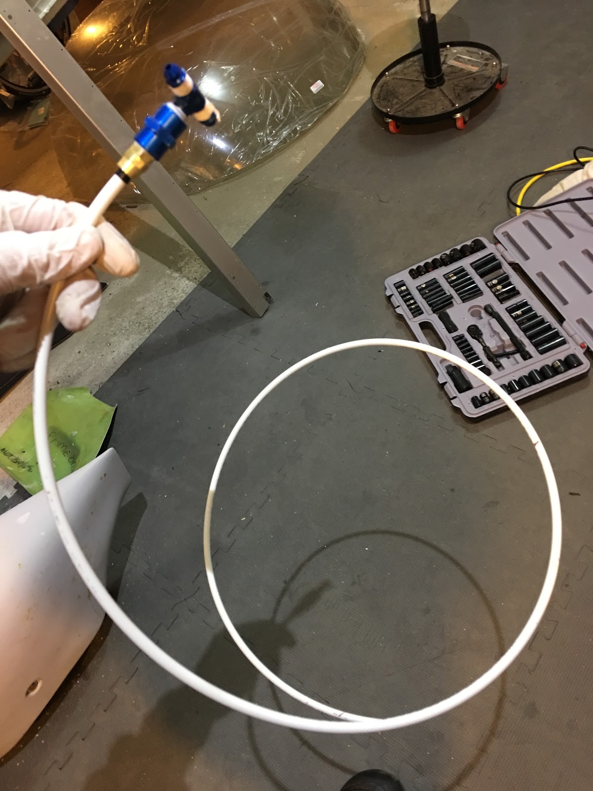
I thought it would be a good idea to use some of the conduit I have to put the brake lines through.  This way if I ever need to replace the lines it will be easy to route through.  The floor over this area is riveted down, so I won't have easy access.
You can notice here that the walls of the center channel are warped.  I noticed this after I had put it on it's gear and kind of freaked.  But, I looked through factory photos and found some others had this same thing.  Not all though, so you may or may not see this.  Once the cover is on that channel, it won't be seen, so I don't care.

I did notice that screwing the brake lines onto the T they seemed to bottom out before reaching the end of the threads. It seems tight, but they got tight abruptly, not progressively like I'd expect it to be.  Normal?...

Well, assuming I don't need to take it back out because of the above noted "issue", then it's in place.  I understand that Bob wrapped his plastic line going forward to protect it, so I may do that too.

Monday, December 24, 2018

Just an hour today working on the brake lines.

Got my package of parts today from Aircraft Spruce.  In there were my parts for the brake lines.  Here's the part for the caliper (not fully installed yet).

Routing the lines under the rear floor.

All the parts (thanks BobZ for the assist!).  One question: The parts shown above the coupler (above the "T") - Do I use the one on the right or left?  I can't figure out how the one on the right holds the 1/4" plastic line (whereas the one on the left, you just tighten and it holds the line).  Tightening the one on the right doesn't seem to do anything.  I must be missing something...🤷‍♂️

Pros seem to use this product for thread sealing of hydraulic and air lines.  Seems way better than teflon tape.  See the next pic for the backside.

Will hold up to 12,000 psi.... Seems like enough...  Also, it's impervious to pretty much any liquid or gas.  Any reason I shouldn't use this stuff?

Sunday, December 23, 2018

2 hrs. mostly on the left stick wiring (also did rivet heading sanding for as long as I could stand it... ;-)).

I removed the old stick wiring on both sides, step-drilled the hole larger to accommodate the larger new stick wiring and put in grommets.  I routed the left side part of the way, but not all the way because I want to see how the fuel lines will get routed before doing anything else.

Saturday, December 22, 2018

3.5 hrs. mostly on the brake line pass-throughs.

I was originally going to put a pass-through fixture on the fuselage skin for the brake lines, but that's really not necessary and just another place you can have leaks.  The next option is a simple grommet, but you can't just drill a hole and put a grommet because the pre-made stainless steel lines have AN3 connectors already installed that are bigger than the line itself (unless you use a extra large grommet and are OK with a hole in the fuselage, which I was not).  So, the answer is a split piece of aluminum to hold the grommet with a larger hole in the fuselage underneath for the connector to pass through.

In other news, I received my M8 and M10 x .75 nuts..... Neither fits the dimmer....  The only size I haven't tried is 3/8" - 16.  Why am I not hopeful....

My wake-up call this morning. 😊

The lines arrived this morning.  Nicely done!  They are 50" long.

I cut out pieces that would fit snugly in the existing outer skin cutouts.

Fits (50mm across).

My rough placement plan.  I didn't want the line pass-through to be in the middle because that exactly lines up with the floor inside and I didn't want an interference problem.

Have I mentioned I love step drill bits?  Sizing these holes to just fit the grommet.

Fits!

Pilot holes where the screws will pass through.  No need for precision here as all this won't be visible.

Now drill the holes through the fuselage to locate where the rivnuts and larger pass-through hole will go.

Used the step drill bit again to drill out the pass-through hole.  Fits through nicely.

Drilled and reamed out the holes for the rivnuts and installed them.

Drilled out the holes in the plate to fit the screws and did a test fit.

With all that done it was time to split the plate and do the install.  The grommet actually needs to be split too because you can't fit it over the connector.

And it's installed (both sides done)!  I put blue, medium strength, Loctite on the screws.  In case you're wondering why the upper screws aren't higher, it's because I wanted them close to where the grommet would be.

I have to decide if I want to ream out the channel a bit to fit the line as it's slightly bigger than 1/4".  In any case you do want to leave a bit of slack in the line to account for flexing of the gear.

Friday, December 21, 2018

.5 hr sanding rivet heads (no exciting pictures) and .5 hr working on my electrical connections spreadsheet, which you can see on the Avionics and Electrical Page.

Rotax has issued another update to their ASB with a narrower range of S/N's affected.  Mine still affected?  I don't have the engine (it's at Lockwood), so I don't know.

UPDATE: I've been notified by TAF USA that they believe my engine is no longer in the S/N range requiring the fix.  They're confirming and will let me know.  Good news!

Heard from JimP (thanks Jim!) where he got his wiring for firewall forward, so I ordered 10' each of red and black from here.  That should be more than enough.

Also, got some red and black heat shrink tubing here.  The 3/4" should fit snugly (ordered a quantity of 2 each color), but I also got some 1/2" (ordered a quantity of 1 each color) in case I have some smaller wires that need covering.


Thursday, December 20, 2018

I've been researching what to use for sealing the firewall (any holes, gaps where wires come through, etc.) and came upon what Paul Dye (Editor in Chief of Kitplanes Magazine) recommends for this.

It is 3M Fire Barrier Silicone Sealant 2000+ and it's available on Amazon (and probably your local Home Depot or equivalent).

He says it's far superior to high-temp RTV and other options that people have used.


Wednesday, December 19, 2018

1 hr. misc.

OK, I tried 3/8" - 32 and -24 nuts and neither fit...  Thoughts?  It's getting annoying...

Instead of that I'll fit the fuel selector to the panel.

Lining up the large hole in the face plate with the hole in the panel and making sure the holes are horizontally lined up with the panel, I taped the face plate in place and drilled the holes.  You need to get the up/down right too because the holes have different spacing for the top and bottom.

Perfect.

I recently got my iPad Pro so I tried a test fit.  It fits, but I need to figure out the trick to putting it in with the lightning connector attached.  Here I've flipped the photo so you can see what it will look like.  BTW, the screen on the iPad Pro is amazing.  Foreflight looks fantastic on it.

Sunday, December 16, 2018

3 hrs. misc.

Useful doc I found in my SteinAir panel build box.  I'll post this to the electrical and avionics page too.

Stringing new wiring for the sticks I'm using three 3-core Tefzel wiring.  I labeled them 1, 2 and 3 and this is my assignments.

I was going to use a connector at the bottom of the stick to connect the wiring, so I spent probably 2 hours working on that...  But, I wasn't happy with how it was going, so I decided to just directly wire it.  Grip wires are ready to go with the butt splices in place.

Did 3 at a time.  Before sliding the butt splice in place I wrapped the wires around each other using a lineman's splice.

All done!

And wrapped up...

I decided to put the rivnuts in the fuel selector and saw that M3 rivnuts fit perfectly in the fuel selector itself, but M3 screws are really too small.  M3 screw on the right and M4 on the left.  M4 is the better fit.

Looking through the small install manual for the fuel selector I saw this...  Full size template for drilling the holes - how convenient....

Yeah, well, except it's not....  It's smaller than actual size, so I won't be using that...

Time to ream out the holes to M4 rivnut size.

And all the M4 rivnuts are in. 😎

Now that fits very nicely.  I'll drill the holes in the dash tomorrow.