Subcribe to our RSS feeds Join Us on Facebook Follow us on Twitter Add to Circles

Categories

Wednesday, November 29, 2017

1 hr. severing the wiring of the right wing to string it through the fuselage.

Other end pinned up so I can check continuity, and new labels printed.

Outer sheath cut away and ready for the surgery...

Cut one wire and figure out which this is.

After that first one the rest were easy because they were different numbers of cores.

Cut off and into the fuselage!  Will do the left wing next, then I need single core wire for the fuel sender wires (what about ground?) in each wing, then pitot heat wires and pitot tubes...   THEN all the wiring and tubing through the fuselage is DONE!

Tuesday, November 28, 2017

Heard from SteinAir today and they're starting on my panel design!  :-)  Better get busy on the plane...  Back in the garage tomorrow!

Meanwhile I'm starting to go through my various pages to update them and generally improve them.  Today I started with the Education Page, where I list the best materials/books for building and flying airplanes.  I specifically added links for all the flying books I think are the best, so it's easier to find them.

If you have any particular flying books you think should be added to my list, let me know by commenting on this post!


So, I heard back from the factory on the wing wire routing in the fuselage.

It looks like it passes to the front of the main spar by going through the first large opening in it.  Once it's in front of the spar it's easy to get to the center.

Factory photo:

Noting the small opening and the sequence of assembly, I'll have to think about my Molex connector approach to make sure I'm not trying to put large connector through that small hole...

Sunday, November 26, 2017

Well, didn't work on the plane today, but I did try a new cool free app, FlyQ Insight.  It's an augmented reality app that you use when you're flying and it shows you where airports are in your field of vision.

Here's a screen shot of it when I was testing it while in my bedroom.  I can see my local airport (where I'll be storing my Sling), 6B6.  You can see it's 3nm beyond my dresser. :-)


They need to fix the symbol for 6B6 because there's no longer a crossing runway...

Saturday, November 25, 2017

1 hr. misc. wiring.

Well, not using the tubing all over the place (too much of a pain to thread it everywhere), but there are some places it's useful.

Tying up all the wiring since this area is finished.

This is what I'll be cutting off.  Note it is behind the main spar (except the fuel sender wire which is in front).

So, the wire bundle from the wing will come in behind the spar, but there's no good way to get to the center behind the spar, so how does it get there?  Maybe under the spar here and then to the center?  Time to ask the factory...  Factory, do you read this? ;-)

Tying up this area too since it's done.

All the wires/tubes from the left wing...

Friday, November 24, 2017

1.5 hrs. finishing up the servo/magnetometer/trim motor wiring.

Making my way through the roll servo connector...

Can Bus daisy-chain.  Ready to solder sleeve the shields together and then the wires.

Done!

All pinned!

Tight, but done.

And it's in!  Glad that wiring is done!  Next I'll do the wing wires and tubes and then the fuselage wiring/tubing is DONE!

Tuesday, November 21, 2017

1.5 hrs. finishing up the pitch servo wiring.

Add some more heat shrink tubing to the graft of the trim motor wiring.

Here's the split with panel wires going forward and the motor control crossing the fuselage to the pitch servo.

Over and pinned (I'm holding the CAN Bus wires done the other day).

Let's not forget the required Pitch Strap wires for the pitch servo...

Jumpered.

Putting on some heat shrink and loom (is that the right word?) for the wires going to the panel.

Now it all comes together...

Tight, but it fits!

Shell on and ready to go.

Very tight squeeze getting the connector in there and tightened down.

Added some tie wraps and it's looking good!  On to the roll servo...

Sunday, November 19, 2017

1.5 hrs on the pitch servo connector.

Power and ground 2-core wire pinned.

Check my work?  Like all the wiring, I'm checking continuity before committing to the connector.

The 5-core wire bundle from the pitch trim motor.

We want the two white wires to go to the pitch servo.  The others go on to the panel.

I started to try and cut the cover off and quickly realized there was no way I was going to cut it all down the length I needed to...

So, instead I cut the two white wires and grafted on another 2-core wire that will go to the servo.

Graft complete and heat shrink on for strength.  I'll add more heat shrink tomorrow for added strength here.

This is how far I got today with the pitch servo connector.  Just need to connect the trim wires and the CAN Bus wires I did yesterday and that's it.

Saturday, November 18, 2017

1 hr. installing the GMU 11 magnetometer connector and stringing the wires.

Brought my super magnet to Home Depot so I could find hardware for the magnetometer connector that wasn't paramagnetic (tested 3 different screws and only this type wasn't paramagnetic).  Double-checking here.  Needed a machine screw (#8-32), washer and terminal lug.  All good to go!

And the shield is connected (medium Loctite on the screw).  Before putting it in I did an end-to-end continuity test on all the wires for this connector.  All good!

Put medium Loctite on the screws and tightened it down.  It is very solidly connected and will not move.  Tied up the wires after this picture was taken.

Stringing my daisy-chain CAN Bus wires to the pitch servo area.

The wire coming from the pitch servo daisy-chain goes to the roll servo and the length is near perfect.

Materials out for the pitch servo and I'll tackle that tomorrow.

Friday, November 17, 2017

1.5 hrs on more wiring!

Decided to put some heat shrink tubing on the GMU 11 connector wiring.  Neater.

Nice!

Some medium strength Loctite on the screws...

And on it goes.

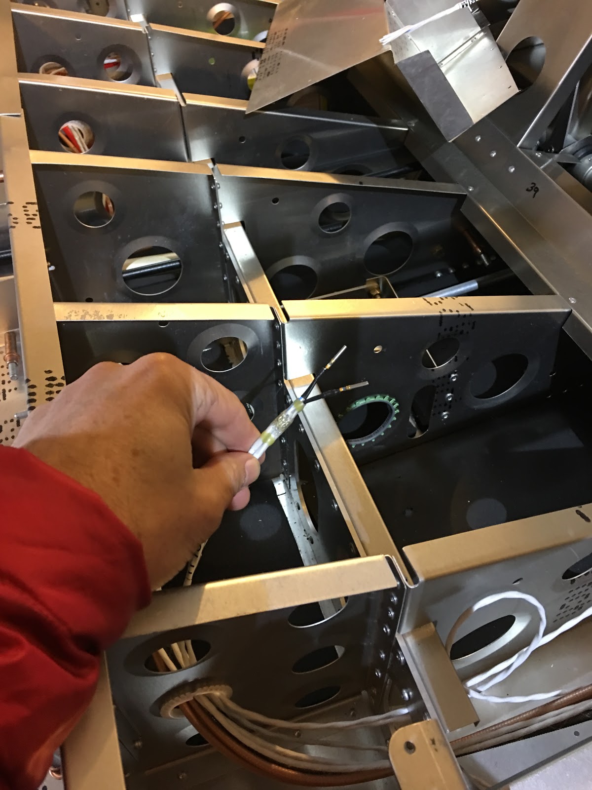
Let's put the connector on temporarily so I can measure out the wire to the pitch servo.

Routed through and I'll cut it to length.

Pull the connector off and pulled the wires back out.  Label the other end so we don't forget what's what...

Now this will be a bit tricky because this is the CAN Bus and it needs to be daisy-chained and the shields connected together.  The exposed wire is longer than needed for the crimp because I'll solder the next link in the daisy chain to it.

Other wire (Pitch servo to roll servo) striped, the shields put together, and then soldered together with solder sleeve.  I checked the shield connection with an ohmmeter end to end and it was good.

Wrap the shorter wires around the longer wires and soldered together.  Make sure the CAN Bus is connected properly: Hi to Hi (blue stripe wires) and Lo to Lo (white).

Wires trimmed to length (keep the two wires the same length or it could be difficult to insert the pins), pins crimped on and heat shrink tubing on.  And we have a CAN Bus daisy chain!  Nice!