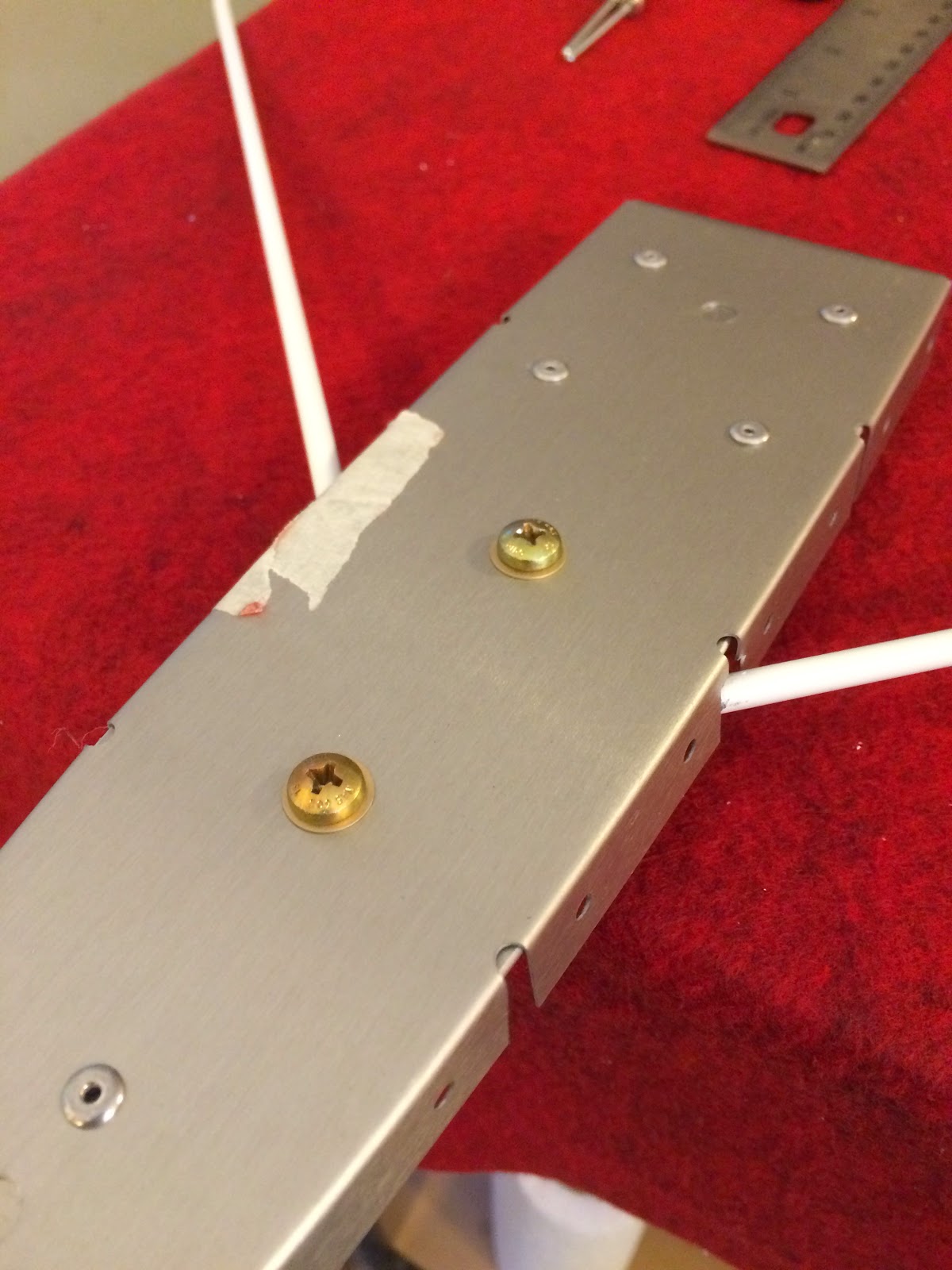
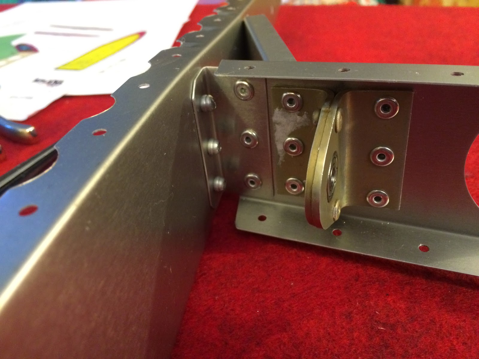
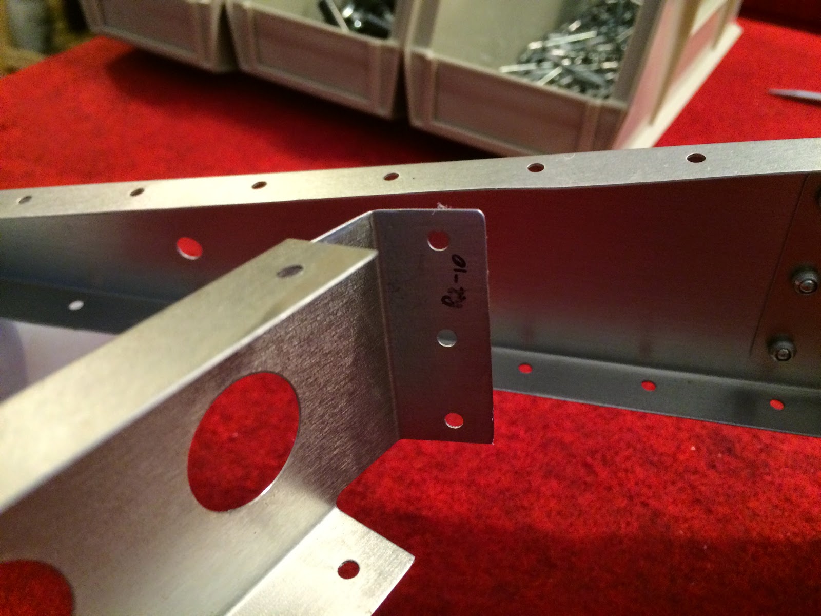
1 hr. deburring the skins of the VS and rudder and making the cable for the VOR.
Here's the crimping tool I got from SteinAir (with the appropriate sized jaws)
And the finished cable! I posted a video a couple of weeks ago about how to make this. If you look for the tag "Avionics" you'll find it.
Categories
ailerons
(16)
avionics
(141)
electrical
(180)
elevator
(23)
Empennage
(55)
firewall forward
(222)
flaps
(12)
fuel cells
(68)
fuselage
(596)
horizontal stabilizer
(14)
instructions
(3)
interior
(104)
paint
(36)
Painting Planes
(3)
panel
(67)
propeller
(3)
rudder
(16)
seats
(5)
ServiceBulletin
(1)
shop
(33)
Sling Central
(23)
tools
(41)
vertical stabilizer
(20)
video
(37)
welcome
(22)
wheels
(44)
wings
(147)
Monday, November 3, 2014
Friday, October 24, 2014
2 hrs finished up the fabrication of the top rib of the vertical stabilizer which contains the VOR antenna, created the holes in the skin through which the antenna and hex key pokes through and riveted the rib to the mounting channel.
Make sure the skin is on and lined up for marking the inside of the skin where it will be drilled through.
View on the inside where it will be marked for the antenna hole and hex key hole. A set for each side.
Marked off for drilling and filing.
After a couple of test fits and lots of filing to fine-tune it, it fits!
Ready to be attached. But first I needed to drill into the 4 rivet holes nearest the VOR "puck" so that the shortened rivets can be inserted.
And it's riveted on! Next I'll construct the cable for the VOR, snake that through (how did Gordon do it?) and snake the 4-core lighting wire through the grommets already installed.
Make sure the skin is on and lined up for marking the inside of the skin where it will be drilled through.
View on the inside where it will be marked for the antenna hole and hex key hole. A set for each side.
Marked off for drilling and filing.
After a couple of test fits and lots of filing to fine-tune it, it fits!
Ready to be attached. But first I needed to drill into the 4 rivet holes nearest the VOR "puck" so that the shortened rivets can be inserted.
And it's riveted on! Next I'll construct the cable for the VOR, snake that through (how did Gordon do it?) and snake the 4-core lighting wire through the grommets already installed.
Wednesday, October 22, 2014
1.5 hrs working on the VS. Continuing work on the top rib for the VOR antenna install.
Taped off around the antenna so I know where on the skin to cut the exit hole.
Just got these precision files today - just in time for the fine-tuning of the holes in the flanges of the rib. I added a new tag word, "tools" for any tool related posts.
Here's the taped-off hole and the drilled and filed hole for the hex key (where the line is drawn vertically so I knew where the pilot hole would be drilled).
The hex key fits!
Taped off around the antenna so I know where on the skin to cut the exit hole.
Just got these precision files today - just in time for the fine-tuning of the holes in the flanges of the rib. I added a new tag word, "tools" for any tool related posts.
Here's the taped-off hole and the drilled and filed hole for the hex key (where the line is drawn vertically so I knew where the pilot hole would be drilled).
The hex key fits!
Sunday, October 19, 2014
1.5 hrs working on the VOR installation on the top rib of the VS.
For connecting the stiffener plate to the top rib why was I getting these mis-drilled holes? I was keeping the drill straight and it was a new bit, so I don't understand. The rivets were tight and there was more than necessary so I'm not concerned about the security of the mating.
Plate connected and the VOR in place for the drilling of the mounting holes for it.
Drilled (3/16" drill bit) and in place. Nice!
What the flip side looked like. Next up will be the placement and drilling of the small holes (one on each side) for the hex key to be able to be inserted (tightening with the key secures the antenna in place).
For connecting the stiffener plate to the top rib why was I getting these mis-drilled holes? I was keeping the drill straight and it was a new bit, so I don't understand. The rivets were tight and there was more than necessary so I'm not concerned about the security of the mating.
Plate connected and the VOR in place for the drilling of the mounting holes for it.
Drilled (3/16" drill bit) and in place. Nice!
What the flip side looked like. Next up will be the placement and drilling of the small holes (one on each side) for the hex key to be able to be inserted (tightening with the key secures the antenna in place).
Saturday, October 18, 2014
1.5 hrs test fitting the skin on the rudder and riveting the rudder structure.
Testing the hinge connections of the vertical stabilizer to the rudder. Good to go!
Test fit of the skin on the rudder.
Hmm, a twist of the trailing edge. I think when I'm going to rivet the skin I just need to be cognizant of any twist of the trailing edge.
Detail photo of the bottom of the mounting channel of the rudder.
Bottom of the rudder.
Note how the bends of that bottom piece point up.
Detail of the top of the rudder channel.
Now with the top rib installed.
Uh oh... The holes are missing from the bottom two ribs for the connection of the strengthening rib. Perhaps I got the Sling 2 ribs? I'll have to figure out how to locate where to drill the holes...
Testing the hinge connections of the vertical stabilizer to the rudder. Good to go!
Test fit of the skin on the rudder.
Hmm, a twist of the trailing edge. I think when I'm going to rivet the skin I just need to be cognizant of any twist of the trailing edge.
Detail photo of the bottom of the mounting channel of the rudder.
Bottom of the rudder.
Note how the bends of that bottom piece point up.
Detail of the top of the rudder channel.
Now with the top rib installed.
Uh oh... The holes are missing from the bottom two ribs for the connection of the strengthening rib. Perhaps I got the Sling 2 ribs? I'll have to figure out how to locate where to drill the holes...
Subscribe to:
Posts (Atom)