2 hrs. disassembling fuel tanks, pulling plastic and working on fuel sender floats.
Disassembled (it was only temporarily put together to test fit and ream holes) and plastic all pulled off.
Sender floats need to be cut to size and bent. I had to reverse one of the rod to plastic ball connections since they will be mirror images.
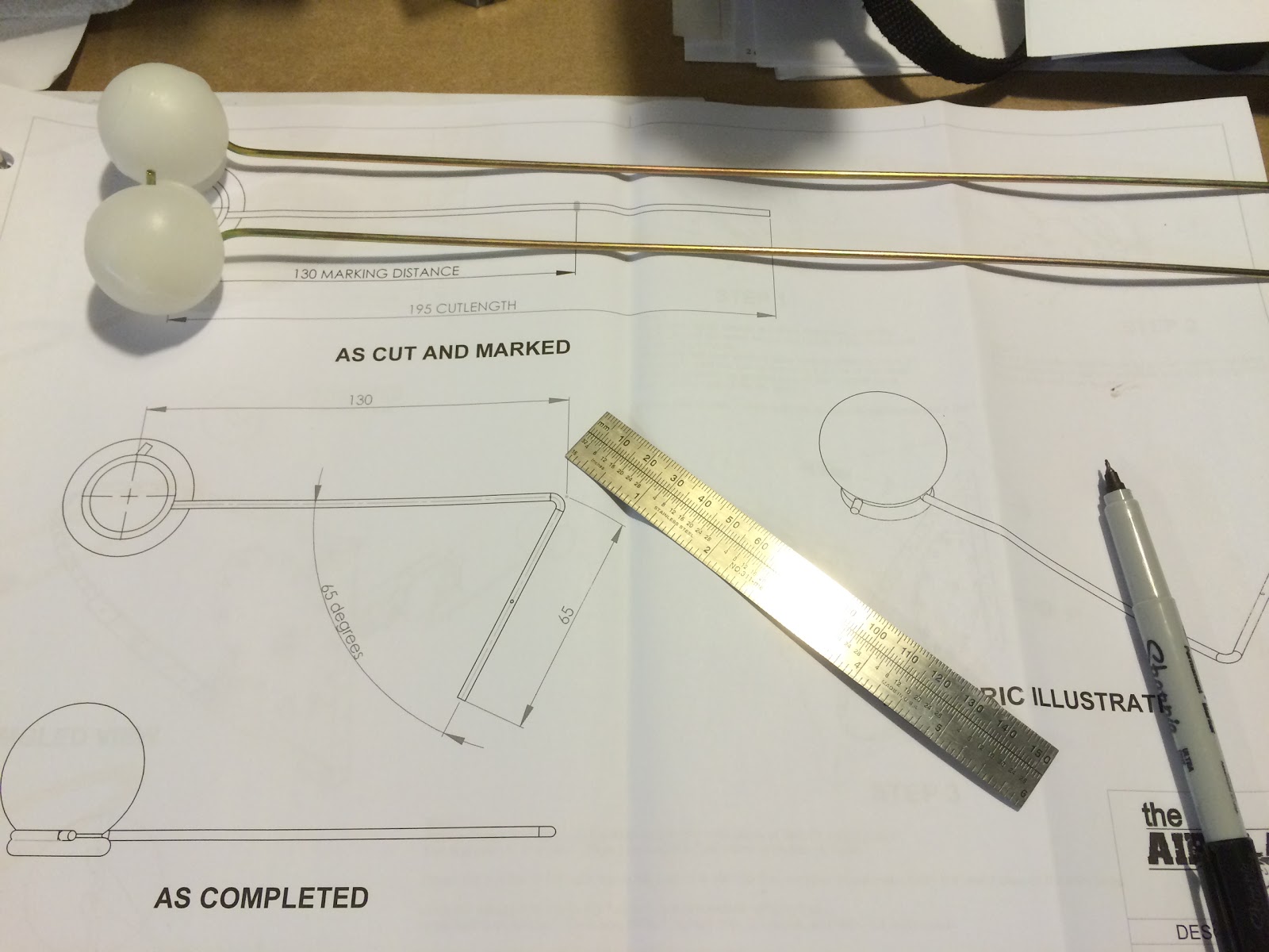
Measured out the cut and bend points.... But....
Use a ruler, the instructions are Not to Scale!
Starting the bend (still trying to figure out the best method of bending the rod - seems like it should be simple, but it's very stiff and it's the first time I'm doing it.). Mostly using a vise, but I'm not convinced I'm doing it the best way to avoid a non-straight bend.
Categories
ailerons
(16)
avionics
(141)
electrical
(180)
elevator
(23)
Empennage
(55)
firewall forward
(222)
flaps
(12)
fuel cells
(68)
fuselage
(596)
horizontal stabilizer
(14)
instructions
(3)
interior
(104)
paint
(36)
Painting Planes
(3)
panel
(67)
propeller
(3)
rudder
(16)
seats
(5)
ServiceBulletin
(1)
shop
(33)
Sling Central
(23)
tools
(41)
vertical stabilizer
(20)
video
(37)
welcome
(22)
wheels
(44)
wings
(147)
Tuesday, June 30, 2015
Sunday, June 28, 2015
2.5 hrs. reaming all the holes in the fuel tanks.
It was recommended to ream out all the holes to size before doing the Prosealing and riveting. Doing that when it's got wet Proseal all ready to be riveted would have been a major mess. Better to do it now!
Using my chucking reamer to ream the holes.
It was recommended to ream out all the holes to size before doing the Prosealing and riveting. Doing that when it's got wet Proseal all ready to be riveted would have been a major mess. Better to do it now!
Using my chucking reamer to ream the holes.
Monday, June 22, 2015
Removed the original piece out of the sender (is that what it's called?).
Part from kit inserted and wire assembly temporarily connected to part.
Got my Proseal today! Away for a few days and then when I return it'll be time to build the tanks!! Was told by a fellow Sling builder about some good tips here. Thanks Bob!
Friday, June 19, 2015
1.5 hrs. working on the fuel tanks. Starting by cleco'ing the ribs into the skins. Note that the fuel tanks will NOT be primed. Just cleaned.
Put the skin in the jig.
Voila! :-)
I forgot to post this the other day. I bought a high sensitivity torque wrench to measure the friction drag torque when I'm putting on nuts. I have a click wrench for putting them on but you can't use that to measure the friction drag torque of the nuts before it's tightened. You need to add that measured amount to the native torque value for the bolt you're using as your final torque value.
The way I measure the friction drag torque is to put the nut on the bolt down near where it will finally rest and turn it slowly with this torque wrench and see what it measures (I saw 5 in-lbs for the last one I tightened). Then I add that amount to the native torque value from the torque chart for the AN bolts and that's my final total torque that I dial into my click-type torque wrench.
Here's Van's torquing instructions and torque chart for AN bolts.
Put the skin in the jig.
A video showing how I cleco the ribs to the skins of the fuel tanks. This is the last rib going on. The first one is the hardest and you should be careful pushing down and aligning the rib so as to not buckle the rib.
Voila! :-)
I forgot to post this the other day. I bought a high sensitivity torque wrench to measure the friction drag torque when I'm putting on nuts. I have a click wrench for putting them on but you can't use that to measure the friction drag torque of the nuts before it's tightened. You need to add that measured amount to the native torque value for the bolt you're using as your final torque value.
The way I measure the friction drag torque is to put the nut on the bolt down near where it will finally rest and turn it slowly with this torque wrench and see what it measures (I saw 5 in-lbs for the last one I tightened). Then I add that amount to the native torque value from the torque chart for the AN bolts and that's my final total torque that I dial into my click-type torque wrench.
Here's Van's torquing instructions and torque chart for AN bolts.
Tuesday, June 16, 2015
1 hr. Starting prep of fuel tank parts.
Gordon has graciously lent me his fuel tank jigs. Thanks Gordon!
Plastic removed from most of the fuel tank parts (both sides).
This is the fuel sender as it comes out of the package (on the right). The part on the left replaces the metal part inserted in the black plastic part. See Gordon's below.
I visited Gordon last night (very helpful!) and he showed me what the fuel sender looks like after you replace the part shown above.
Gordon has graciously lent me his fuel tank jigs. Thanks Gordon!
Plastic removed from most of the fuel tank parts (both sides).
This is the fuel sender as it comes out of the package (on the right). The part on the left replaces the metal part inserted in the black plastic part. See Gordon's below.
I visited Gordon last night (very helpful!) and he showed me what the fuel sender looks like after you replace the part shown above.
Sunday, June 14, 2015
1 hr. playing with Skin 1 on the bottom of the right wing and starting prep of the fuel tank parts.
As I mentioned in my last post the rivet lines on the main spar didn't seem to line up, so I un-cleco'ed all of skin 1 to see if I could get things lined up. No Joy... No matter how I slid it around there was no way the two rivet lines were going to line up. This was the closest I could get them and it's clear something is wrong... The skin holes are about 48mm on center. The spar holes are close to 52mm on center. 4mm difference seems to me a bridge too far. So, either the skin is wrong or the spar (hope not).
Zoomed out view to see where I was measuring. Right bottom wing skin 1 near the root.
As I mentioned in my last post the rivet lines on the main spar didn't seem to line up, so I un-cleco'ed all of skin 1 to see if I could get things lined up. No Joy... No matter how I slid it around there was no way the two rivet lines were going to line up. This was the closest I could get them and it's clear something is wrong... The skin holes are about 48mm on center. The spar holes are close to 52mm on center. 4mm difference seems to me a bridge too far. So, either the skin is wrong or the spar (hope not).
Zoomed out view to see where I was measuring. Right bottom wing skin 1 near the root.
Saturday, June 13, 2015
2 hrs. Test fitting skins on bottom of right wing.
Checked for squareness of jigs and then checked the alignment of the ribs with the skin... Not lined up on the main spar side! Had to slide the main spar ends of the jigs to the right. Notice how the skin holes don't line up with the rib underneath.
After sliding the main spar ends of the jigs - lined up! :-)
All cleco'ed up! Looks good.
Well except for the end of the main spar near the root... The holes don't quite line up. If I un-cleco'ed the whole skin and re-cleco'ed starting from this end could I make up that distance and have everything still fit? If anybody knows, please email me.
Checked for squareness of jigs and then checked the alignment of the ribs with the skin... Not lined up on the main spar side! Had to slide the main spar ends of the jigs to the right. Notice how the skin holes don't line up with the rib underneath.
After sliding the main spar ends of the jigs - lined up! :-)
All cleco'ed up! Looks good.
Well except for the end of the main spar near the root... The holes don't quite line up. If I un-cleco'ed the whole skin and re-cleco'ed starting from this end could I make up that distance and have everything still fit? If anybody knows, please email me.
Subscribe to:
Posts (Atom)


