4 hrs. misc.
Adding to my collection of crimpers... CP-251B for 22 to 6AWG and CP-351B for 8 to 2AWG.
Also got my 50 AMP fuse for the external alternator and a mounting block.
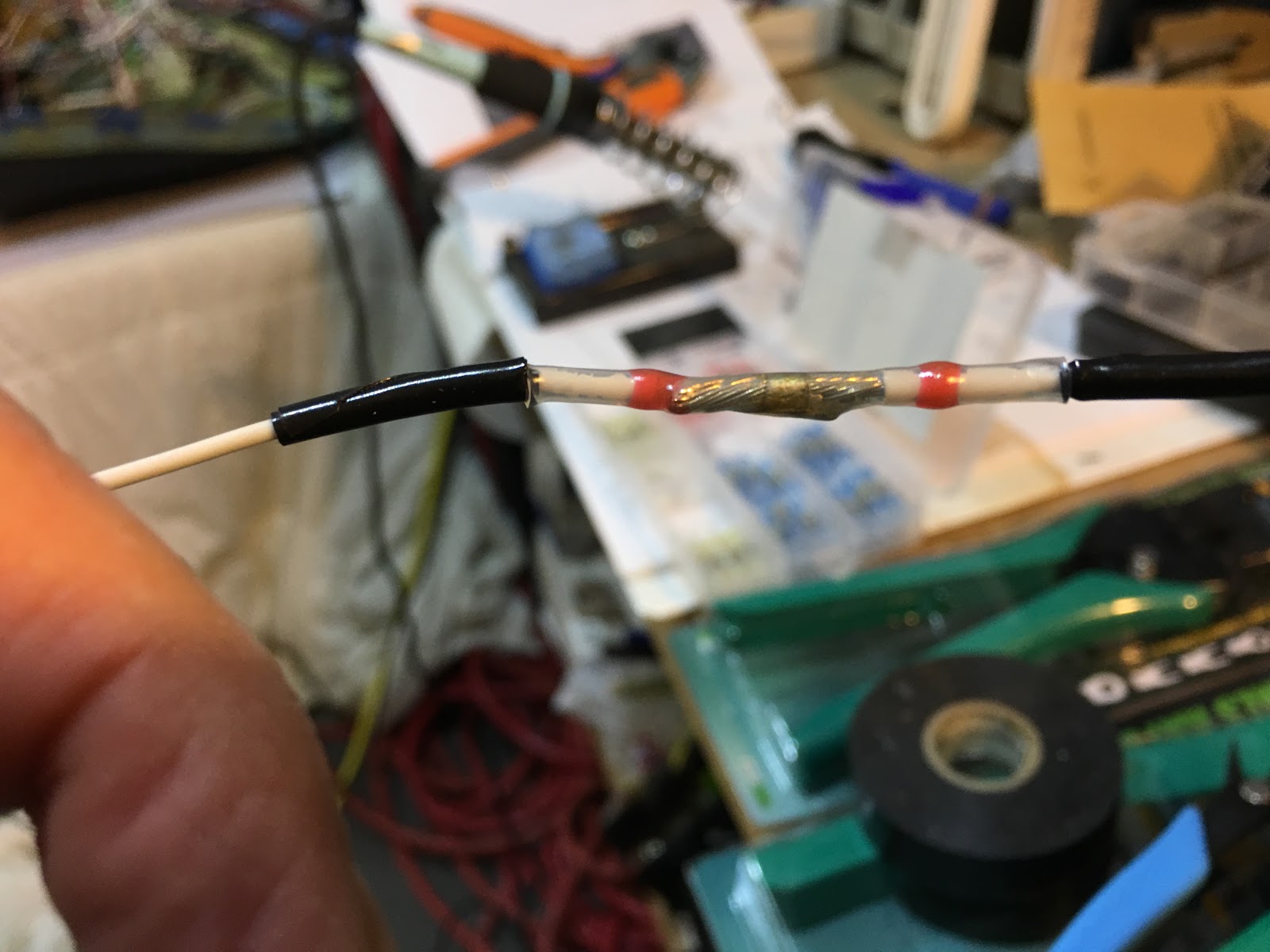
Extending the wires for the overhead lighting with butt splices.
Routing them (it's just power and ground) toward the front...
...and a test at the front confirms continuity. 😁
Bought some tie downs for the luggage area.
No pics but I also started to make new wiring trunks for the sticks since I have a few more buttons than I originally planned.
Categories
ailerons
(16)
avionics
(141)
electrical
(180)
elevator
(23)
Empennage
(55)
firewall forward
(222)
flaps
(12)
fuel cells
(68)
fuselage
(596)
horizontal stabilizer
(14)
instructions
(3)
interior
(104)
paint
(36)
Painting Planes
(3)
panel
(67)
propeller
(3)
rudder
(16)
seats
(5)
ServiceBulletin
(1)
shop
(33)
Sling Central
(23)
tools
(41)
vertical stabilizer
(20)
video
(37)
welcome
(22)
wheels
(44)
wings
(147)
Saturday, December 15, 2018
Tuesday, December 11, 2018
Half hour to take measurements for the brake lines.
I'm going to use the included plastic tubing from the reservoir through the brake cylinder assembly, back to the "T". From there it will be stainless steel lines.
This is the supplied "T". From the T to the fitting which will go through the fuselage skin is 20". That has a small bit of margin to account for a slight bend to the fitting.
Then it goes through the fitting to the outside. I used my handy boroscope, which is stiff, so it works well for this measurement. From the end at the fuselage to the brake fitting is a bit less than 27 3/4". The gap in the gear leg for the brake line is 1/4". Not sure the SS brake lines will fit into that gap.
I'm pretty sure the nipple which is on the bottom of this brake needs to moved to the top. I measured to roughly where the fitting will be.
Close up at this end. Unless I hear from anybody out there about how I measured, I will order the lines tomorrow from this company.
I'm going to use the included plastic tubing from the reservoir through the brake cylinder assembly, back to the "T". From there it will be stainless steel lines.
This is the supplied "T". From the T to the fitting which will go through the fuselage skin is 20". That has a small bit of margin to account for a slight bend to the fitting.
Then it goes through the fitting to the outside. I used my handy boroscope, which is stiff, so it works well for this measurement. From the end at the fuselage to the brake fitting is a bit less than 27 3/4". The gap in the gear leg for the brake line is 1/4". Not sure the SS brake lines will fit into that gap.
I'm pretty sure the nipple which is on the bottom of this brake needs to moved to the top. I measured to roughly where the fitting will be.
Close up at this end. Unless I hear from anybody out there about how I measured, I will order the lines tomorrow from this company.
Sunday, December 9, 2018
4 hrs. on the lighting.
To get the wiring to the rear lights I cut a hole in the conduit.
Snaking lots of wires....
Soldering in the lights one-by-one and testing at every step to make sure i still had connectivity.
All connected and working.
While installing each light I continued checking the connectivity. Missing a nut for the dimmer, so I need to get that before installing it.
Well lit! I didn't even realize it, but having the lighting in will really help to see things while I'm working on the interior.
Red... 😁
To get the wiring to the rear lights I cut a hole in the conduit.
Snaking lots of wires....
Soldering in the lights one-by-one and testing at every step to make sure i still had connectivity.
All connected and working.
While installing each light I continued checking the connectivity. Missing a nut for the dimmer, so I need to get that before installing it.
Well lit! I didn't even realize it, but having the lighting in will really help to see things while I'm working on the interior.
Red... 😁
Saturday, December 8, 2018
4 hrs. on the air lines and interior lighting.
While I was waiting for a friend to come over and help I worked on the pitot/static lines behind the panel. Here I'm ratcheting in the push-ons to the AHRS for the G3X. Nice and tight...
Cutting the lines with the Rigid PC-1250. White: Static, Green: Pitot and Blue: AOA.
Put in all the "T"'s and test port plugs. Nice!
Worked like a champ! It helped to have a 3rd helping hand to hold the block in place, but it was super easy to drill into the fiberglass to enlarge the holes to the proper size. Remember to wear a mask and something for your eyes as there's lots of fiberglass dust doing this.
Now to figure out the wire fishing... Using my boroscope, this is the view from the front hole looking back. I'll figure the wire routing out and finish this all tomorrow (at least that's the goal... 😊).
While I was waiting for a friend to come over and help I worked on the pitot/static lines behind the panel. Here I'm ratcheting in the push-ons to the AHRS for the G3X. Nice and tight...
Cutting the lines with the Rigid PC-1250. White: Static, Green: Pitot and Blue: AOA.
Put in all the "T"'s and test port plugs. Nice!
I mentioned the other day that using a hole saw to enlarge preexisting holes wasn't working because there wasn't anything to drill the pilot bit into. Well, while I was lying in bed yesterday morning I came up with an idea. Use the hole saw to drill through a 2x4 and use that as a template over the hole to be drilled. That way the saw won't jump - because it can't. I put on some rubber sheet to protect the fiberglass and make it easier to hold in place.
Worked like a champ! It helped to have a 3rd helping hand to hold the block in place, but it was super easy to drill into the fiberglass to enlarge the holes to the proper size. Remember to wear a mask and something for your eyes as there's lots of fiberglass dust doing this.
Now to figure out the wire fishing... Using my boroscope, this is the view from the front hole looking back. I'll figure the wire routing out and finish this all tomorrow (at least that's the goal... 😊).
Friday, December 7, 2018
My engine arrived at Boston's Logan Airport yesterday, but it didn't make sense for it to be delivered to me since it needs to have the ASB done. So, TAF USA managed to get the shipper to redirect the engine to Lockwood Aviation in Florida (the top Rotax service station in the USA). Much better than receiving it and having to send it back out.
May not see the engine for awhile... Which is OK since I have plenty of other things to get done.
Thursday, December 6, 2018
1 hr. working on the lighting.
Well, I got the hole saws...
...clever attachment mechanism which allows you to adjust how much you want the pilot drill bit to protrude. But.... I tried it and discovered that without something for that pilot bit to drill into, using a hole saw will not work. What happens is the saw's teeth grab the material at one place and the whole thing jumps pretty strongly. I mean maybe if I could put some piece of wood in the hole for it to drill into... But, it can't move... It's just not going to work. Back to grinding the holes to size... Ugh...
Many minutes of grinding later, it's close to fitting...
A bunch more minutes and it fits... I need a better grinding bit...
And the other side is done too. The rear holes will require a good deal more material to remove, so I may need to think about a better way to do it. Any ideas?
Well, I got the hole saws...
...clever attachment mechanism which allows you to adjust how much you want the pilot drill bit to protrude. But.... I tried it and discovered that without something for that pilot bit to drill into, using a hole saw will not work. What happens is the saw's teeth grab the material at one place and the whole thing jumps pretty strongly. I mean maybe if I could put some piece of wood in the hole for it to drill into... But, it can't move... It's just not going to work. Back to grinding the holes to size... Ugh...
Many minutes of grinding later, it's close to fitting...
A bunch more minutes and it fits... I need a better grinding bit...
And the other side is done too. The rear holes will require a good deal more material to remove, so I may need to think about a better way to do it. Any ideas?
Subscribe to:
Posts (Atom)