Mark off 3/8" and 3/4" from the end and carefully take off the insulation from the 3/8" point. I use sharp diagonal cutters for this by putting them around the cable applying a little pressure and rotating it around until you're just through.
Now clip back the shielding nice and cleanly all the way to the outer insulation.
Now carefully cut off the outer insulation at the 3/4" point.
Cut off the inner insulation about 3/32" away from the shield point. You will have to shorten the inner wire to fit in the next step, and that's already shown here.
Put the inner pin on the exposed wire so that it seats against the inner insulation. Like I mentioned above I had to shorten the wire to allow the pin to fully seat.
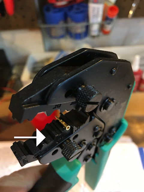
This shows where the pin will sit when you crimp it. The wire, of course, must be in the pin when you do that. The arrow shows the section you'll use for the outer sleeve crimping later.
Pin crimped in place and tug tested. Now the outer sleeve is slid over the cable.
Now take the connector and push it on to the cable until the pin audibly clicks in place. At this point you should use a ohmmeter to make sure the inner pin is isolated from the outer metal.
Slide the sleeve into place and....
Crimp! Crimp it twice at different angles to secure. Tug test and one last ohmmeter test and you're done!


How do you get a good electrical connection between the sleeve and the body of the connector?
ReplyDeleteThe crimp only gives connection to shield and hold sleeve in place?
There's an inner sleeve that's part of the connector body that slides under the shielding. So the crimp pushes together the outer sleeve, shield and inner sleeve. Solid connection.
Delete