3 hrs. working out the sub-panel arrangement and starting to build it out.
The brackets that come with the kit are for an older transponder, and unfortunately they don't work with the GTX 45R ADS-B/Transponder I have.
I was going to put the TCU on the sub-panel, but decided it would be best put on the cabin-side of the firewall near the large pass-through hole (not cut in the soundproofing yet).
After much contemplation and swapping around, I decided on this final arrangement. The center section is completely clear leaving lots of room for the GTN 650 and anything else that will pass through the center.
Another view.
Time to start drilling! Some of these could be held up with M3 screws, but I have better luck with the M4 rivnuts, so I'll standardize on that size.
Rivnuts in for the GEA 24!
And it's in! I'll pass the wiring going to the engine from that box right through that hole.
Next up is the backup battery and that's in too! I'm hoping to finish this all up tomorrow.
Categories
ailerons
(16)
avionics
(141)
electrical
(180)
elevator
(23)
Empennage
(55)
firewall forward
(222)
flaps
(12)
fuel cells
(68)
fuselage
(596)
horizontal stabilizer
(14)
instructions
(3)
interior
(104)
paint
(36)
Painting Planes
(3)
panel
(67)
propeller
(3)
rudder
(16)
seats
(5)
ServiceBulletin
(1)
shop
(33)
Sling Central
(23)
tools
(41)
vertical stabilizer
(20)
video
(37)
welcome
(22)
wheels
(44)
wings
(147)
Saturday, May 19, 2018
Friday, May 18, 2018
1.5 hrs. on the sub-panel mock-up.
Drew the connectors on the boxes so I know what needs to be reachable/accessible.
Initial test arrangement. I immediately see two potential issues. If the 45R's position under the sub-panel is already defined by holes in the firewall and it needs to move further left then it could interfere with the connectors for the 245. The other is the VP-X needs to move left so the connectors on the right side aren't too close to the upright.
Put my panel mock-up in its approximate location. :-)
Another view.
And yet another...
Behind the sub-panel.
Here's looking up and you can see the potential issue between 45 and 245.
Drew the connectors on the boxes so I know what needs to be reachable/accessible.
Initial test arrangement. I immediately see two potential issues. If the 45R's position under the sub-panel is already defined by holes in the firewall and it needs to move further left then it could interfere with the connectors for the 245. The other is the VP-X needs to move left so the connectors on the right side aren't too close to the upright.
Put my panel mock-up in its approximate location. :-)
Another view.
And yet another...
Behind the sub-panel.
Here's looking up and you can see the potential issue between 45 and 245.
Thursday, May 17, 2018
2 hrs. constructing mock-ups of the remote boxes.
First I tried a clever method for making the boxes, then I tried the brute force method. The brute force method is faster...
The clever method was to figure out the pattern to cut a box from one piece. Takes awhile to draw it all out...
Cut out...
And taped together. Came out well.
I decided to try the brute force method of just cutting to size the four longer sides individually...
And taping them together on the inside...
Then just eyeball the two end pieces. Much quicker and comes out just as well as the "clever" method, maybe even better...
All done! Will start trying things out tomorrow.
The box sizes I used, which includes the connectors, but not the mounting flanges:
First I tried a clever method for making the boxes, then I tried the brute force method. The brute force method is faster...
The clever method was to figure out the pattern to cut a box from one piece. Takes awhile to draw it all out...
Cut out...
And taped together. Came out well.
I decided to try the brute force method of just cutting to size the four longer sides individually...
And taping them together on the inside...
Then just eyeball the two end pieces. Much quicker and comes out just as well as the "clever" method, maybe even better...
All done! Will start trying things out tomorrow.
The box sizes I used, which includes the connectors, but not the mounting flanges:
GEA 24: 5.75" L x 3.25" W x 2" D
GTR 20: 8.25" L x 6.25" W x 1.25" D
GMA 245R: 6.75" L x 6.25" W x 1.5" D
TCW IBBS-12V-6AH Backup Battery: 7" L x 2.25" W x 2.75" D
GTX 45R: 9" L x 6.25" W x 1.75" D
VP-X: 8" L x 6.75" W x 2" D
Tuesday, May 15, 2018
Just .5 hr. contemplating...
The manual shows that rivnuts also go in these two holes, but in thinking about it I realized that the rudder spar will have to slide down into this slot, so better to not install anything that sticks into that path. After the rudder is on would probably be the time to put in that rivnut.
No picture, but was just thinking further about the remote box arrangement on the sub-panel. I decided it makes sense, like other builders have done, to build some full size cardboard boxes for all the boxes to mock up the arrangement. Easier than trying to figure it out with the actual boxes.
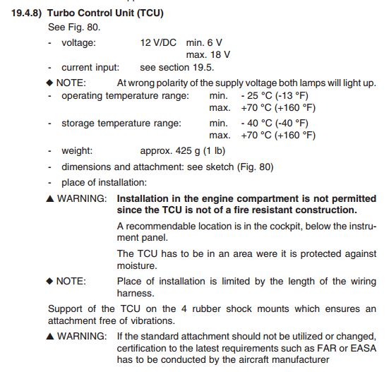
As I mentioned, the Rotax manual says the TCU must be mounted inside the cabin, so I'll plan to do that. Jim also pointed out to me that the Rotax manual also says to mount the waste gate servo motor inside the cabin, so that needs to be figured out.
Time to update my Task List...
BTW, I just realized that I recently passed 1000 hours on the build! :-)
The manual shows that rivnuts also go in these two holes, but in thinking about it I realized that the rudder spar will have to slide down into this slot, so better to not install anything that sticks into that path. After the rudder is on would probably be the time to put in that rivnut.
No picture, but was just thinking further about the remote box arrangement on the sub-panel. I decided it makes sense, like other builders have done, to build some full size cardboard boxes for all the boxes to mock up the arrangement. Easier than trying to figure it out with the actual boxes.
As I mentioned, the Rotax manual says the TCU must be mounted inside the cabin, so I'll plan to do that. Jim also pointed out to me that the Rotax manual also says to mount the waste gate servo motor inside the cabin, so that needs to be figured out.
Time to update my Task List...
BTW, I just realized that I recently passed 1000 hours on the build! :-)
I noticed that the factory installs the 914's TCU on the engine side of the firewall, but this is prohibited in the Rotax Installation Manual. I consulted with the factory and they indicated that installing it instead on the sub-panel should be fine as the wiring harness is of sufficient length to reach there.
I will leave space on the right side of the sub-panel for the TCU install.
Sunday, May 13, 2018
Mother's Day, so only 1 hr today. ;-)
Starting to play with arrangement of the remote boxes...
The 650 is fairly wide and deep, so I probably need to rearrange the remote boxes...
...to be more like this. But, is there room behind the 650 for the backup battery which is somewhat deep?
I'll leave a 10" wide swath of space for the 650.
I do want to have the boxes out a bit so I can more easily remove them by sliding them down, so they need to be beyond the bottom flange of the sub-panel.
Starting to play with arrangement of the remote boxes...
The 650 is fairly wide and deep, so I probably need to rearrange the remote boxes...
...to be more like this. But, is there room behind the 650 for the backup battery which is somewhat deep?
I'll leave a 10" wide swath of space for the 650.
I do want to have the boxes out a bit so I can more easily remove them by sliding them down, so they need to be beyond the bottom flange of the sub-panel.
Saturday, May 12, 2018
2 hrs. on the empennage control cover. I decided that instead of waiting for a new one I would simply match drill the blank one I have (I was told by Peter that they were identical).
Tomorrow I'll work on the sub-panel to start constructing brackets for mounting the remote boxes.
Got an angle grinder from Harbor Freight ($19 on sale!) and the cutter recommended by Jim Pavlick for the canopy work.
Ready to match drill...
Cleco'ed as I went along...
All the screw holes drilled and drilling and reaming out the larger holes...
And it's done!
Two rivets needed to be drilled out and reamed out to accommodate M3 rivnuts.
And they're on. It does look like another rivet will need to be drilled out and replaced with a rivnut though.
Found the list Sika products I'll need. Jim mentioned an activator so I'll have to look into that. BTW, the 209 N is no longer produced and is now the 209 D.
Meanwhile the Sikaflex (295 UV) I bought last year (in July) is now expired, so is no longer usable... :-( I'll wait until I'm ready to put on the canopy before buying...
Tomorrow I'll work on the sub-panel to start constructing brackets for mounting the remote boxes.
Got an angle grinder from Harbor Freight ($19 on sale!) and the cutter recommended by Jim Pavlick for the canopy work.
Ready to match drill...
Cleco'ed as I went along...
All the screw holes drilled and drilling and reaming out the larger holes...
And it's done!
Two rivets needed to be drilled out and reamed out to accommodate M3 rivnuts.
And they're on. It does look like another rivet will need to be drilled out and replaced with a rivnut though.
Found the list Sika products I'll need. Jim mentioned an activator so I'll have to look into that. BTW, the 209 N is no longer produced and is now the 209 D.
Meanwhile the Sikaflex (295 UV) I bought last year (in July) is now expired, so is no longer usable... :-( I'll wait until I'm ready to put on the canopy before buying...
Subscribe to:
Posts (Atom)