Subcribe to our RSS feeds Join Us on Facebook Follow us on Twitter Add to Circles

Categories

Friday, October 19, 2018

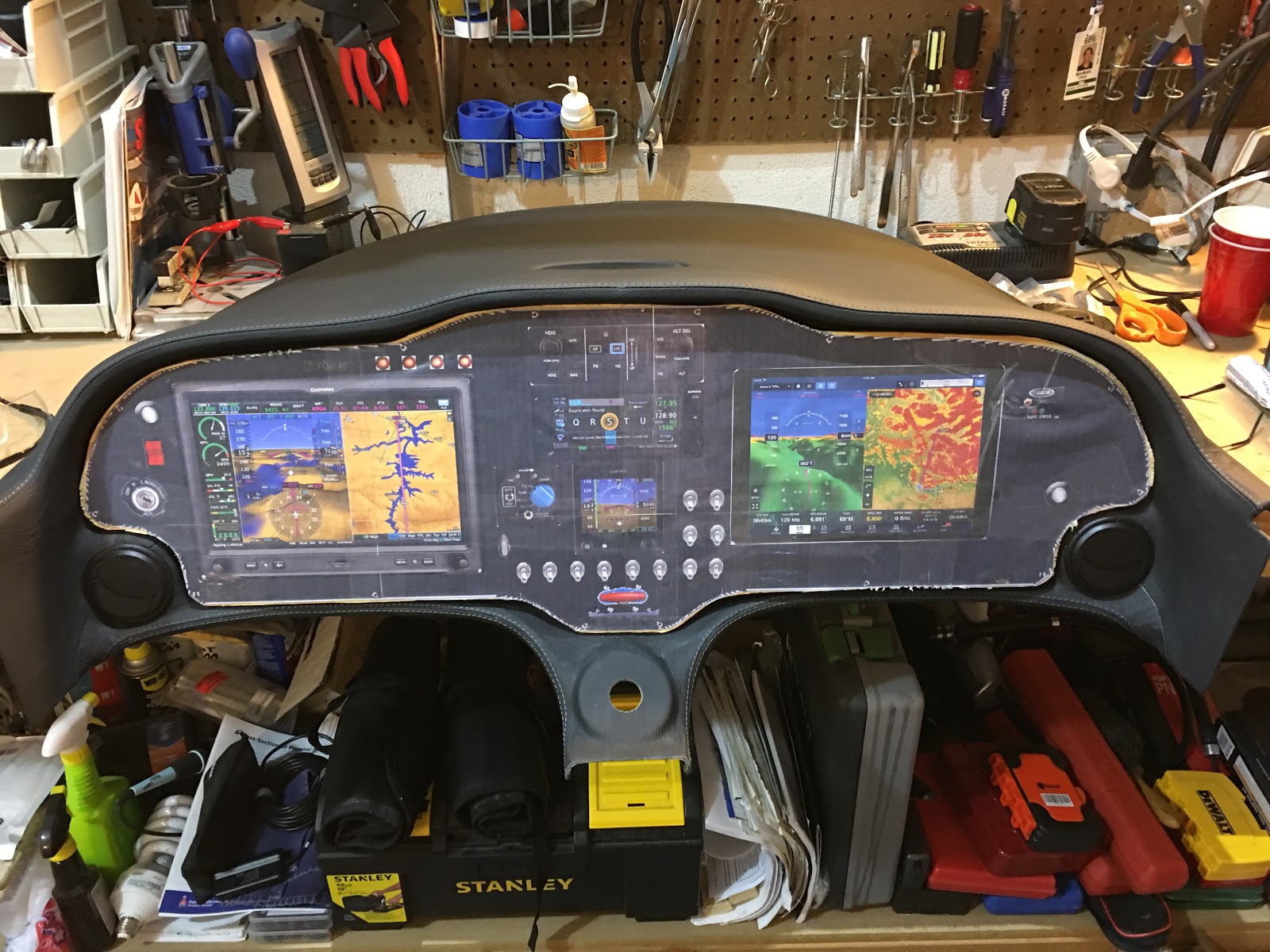
1.5 hrs. mostly on the panel mock-up for the dash.  I did also finally rivet the upright to the sub-panel.

I glued the panel printout (I know I don't really need the printout, I just like the way it looks. ;-)) onto the wood and using a jigsaw cut it out.  Test fit here.

I'm not going to screw in every hole, as a few should do.  Here I'm locating the first few holes.

A few screws in.  I'll probably try and put a few more in tomorrow.

Thanks to Kerry I've now identified terminal connectors that meet the criteria I mentioned previously.

The connectors use nylon insulation and are brazed.  This place has the best prices I've found.

Here's a huge picture of the connector: :-D

Thursday, October 18, 2018

The factory has confirmed for me the vertical positioning for the dash with respect to the fuselage sides.

As shown here, it is 20 mm from the top edge of the interior skin to the top of the dash at the canopy edge.  I did have to push it down a bit from it's natural position to get it to 20 mm.  Note that it would be more accurate to do this measurement on the inside.

Wednesday, October 17, 2018

Half hour working on the panel mock up for the dash.

I bought a 2' x 4' x 1/4" thick piece of hardwood plywood and printed out a new copy of the panel from X-Panel.  Tomorrow night I'll glue it down, cut it out and drill the mounting holes, being careful to get correct positioning of the holes in particular.

I need a 50 Amp fuse for the 914's external alternator, but the only fuses on Aircraft Spruce for that use are 60 Amp, which of course won't do.

Is this one OK?  The 914 Installation Manual only indicates that the fuse needs to be slow blowing, but the description of this fuse makes no mention of that.  What have other people used?  Where did you get it?

UPDATE: It seems the factory (and other builders) use a circuit breaker for this (and possibly other uses in the 914).  They're going to let me know a source and I'll post that here when I have it.

Tuesday, October 16, 2018

I got answers from various people regarding my questions over the last few posts (Thanks to JeanD, SimonK, BobZ, MikeB and PeterC!).

It looks like my fitting issue with the dash is not uncommon and not difficult to solve.  As a matter of fact you can see some of what I see with mine in the 10th and 11th photos on the External Fuselage page of the Factory Photo Pages.  You note that the left and right side come down to different spots on each side.  I think this difference is a "don't care" because it will get covered up by the exterior cover strip (I don't know the actual name of the part).

In terms of the width, another builder had this issue and solved it by screwing in a stiff mockup of the panel and also placing the throttle assembly in place to lock in the lower portion of the dash.  With that done they then used a rope (or strap) with hooks on each end to reel in the outer edges of the dash so it can be properly riveted in place and the windscreen put in.  The factory does it similarly as far as I understand: pushing and pulling as necessary to make it fit.  I'll print out a new actual size panel from my X-Panel mockup and glue that to some 1/4" plywood to cut it out and drill the mounting holes.

As expected, the brake lines do have a tee fitting to go off to each brake.  I think the plan will be to route one line down from the throttle assembly, through the center console and channel and then tee-off just before the lines need to branch to the wheels.  I plan to have braided stainless steel lines custom made for me.  I'll post the details of that when I do it.

For the luggage door I will be getting a larger piece of carpeting so I don't need to de-rivet that angle off the door.  Easier.

Jean mentioned to me that the hole the shoulder washer goes through on the throttle arm needs to be countersunk a bit to allow the nut to be tightened down to hold the throttle cable and still be able to rotate.  So, I have to disassemble that again...

I will look into using plastic grommets (I have a wide selection) for the tow bar holes.  I've seen photos of that hole if it's unprotected and it doesn't fair well.

I will post photos and links for all of the above when I get to each of them.

Monday, October 15, 2018

1 hr. mostly on the throttle assembly.

Thanks to a heads-up from PeterC I found the pre-drilled bolts for the throttle assembly....  These were not called out in the manual and also they were in the firewall forward sub-kit which I did not have at the time of working on this awhile ago.  Well, at least I don't have to drill the holes...

You can't tighten these too much or it would prevent it from rotating as you move the throttle.

Another view.  I was concerned that those nuts could come off since there's no thread showing....

...but as you see here they can't loosen because the throttle handle itself is in the way.

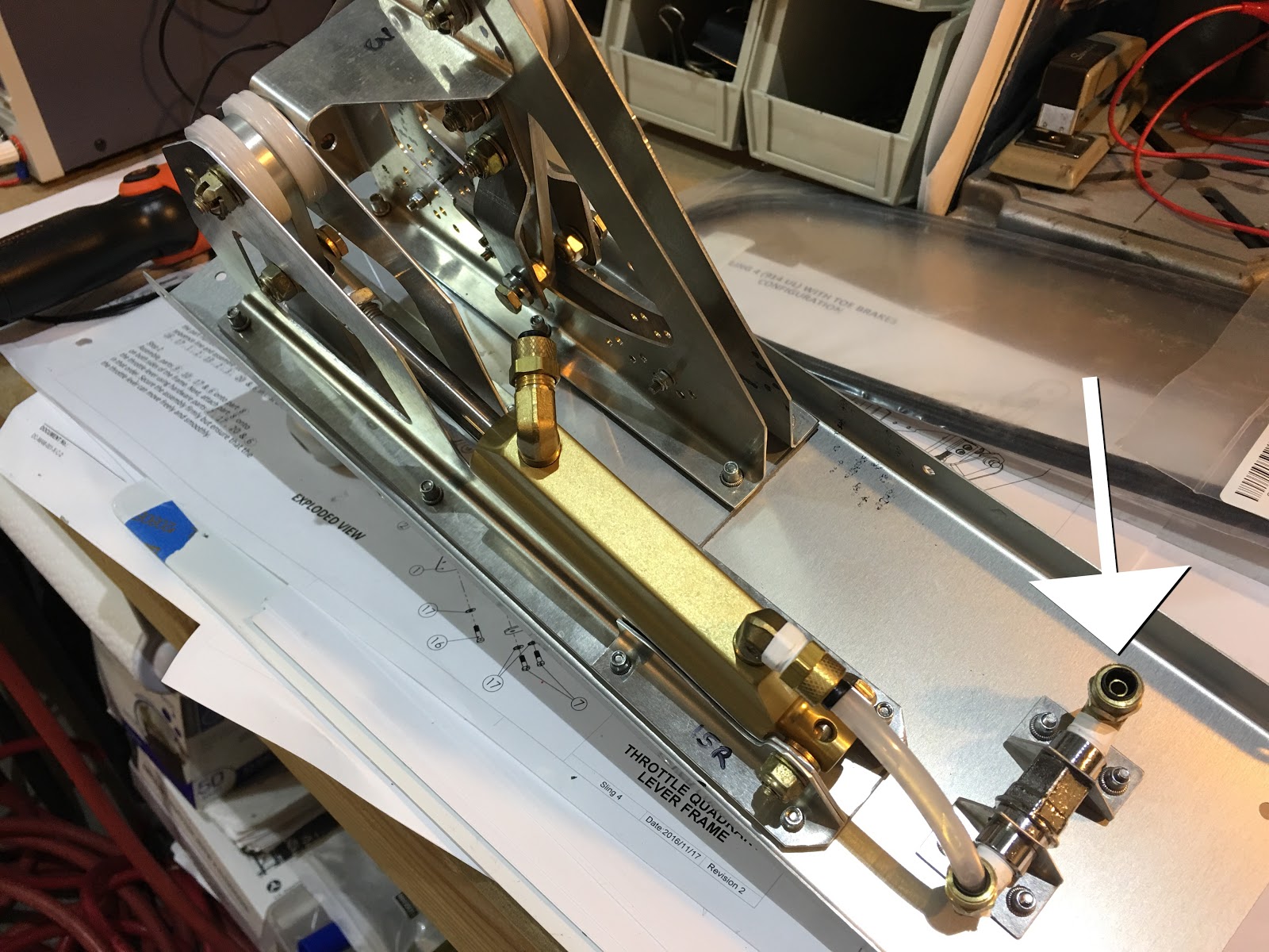
OK, so I assume the brakes get connected to the outlet pointed to here.  Is there a splitter after that to go to the two brakes?  And I assume the other end gets connected to the brake reservoir on the firewall, right?

  Since I'm done with the throttle assembly, what are these for?

I was also alerted by PeterC that the strengthening angle shown here.... is upside down...  The manual is wrong.  :-(  As is, the carpeting supplied would not fit.  Should I just get a larger piece of carpet to fit the larger area or do I de-rivet and flip it?  You'll note that I applied some fluting to get it to curve, so flipping it will only work if it's a symmetrical curve (and the holes are perfectly symmetrical).  I'm tempted to just ask for a larger piece of carpeting.  Jean?