Subcribe to our RSS feeds Join Us on Facebook Follow us on Twitter Add to Circles

Categories

Sunday, August 27, 2017

3 hrs. yesterday removing the magnetometer and making the connector for the ELT.

Since the magnetometer is moving to the rear fuselage (the factory is fabricating a new mount for me) it was time to remove it from under the luggage section.  Gone!

Despite being an electrical engineer, I can't say I enjoy making connectors...  Conveniently the ELT comes with the necessary parts to make it's connector.

I'll be using a 3-wire shielded cable and a 2-wire shielded cable.  Don't forget to put the rubber gasket on first.

Striped and ready to go.

Making sure I know which wires go where.

If I had a third (and fourth!) hand I wouldn't need one of these...  You need one.

Soldering in the required jumper.

Wire in place.  Apply the heat to the connection, not the solder.

My plan as to which colored wires go to which signal.

One-by-one...

I'm bringing a Ground back to the panel and the install instructions say to ground the shield to that.  So, those connections are under the heat shrink tubing.

In the shell and ready to close.

Don't forget to put the attachment screws before putting the other half of the shell on (don't ask how I know this... ;-)).
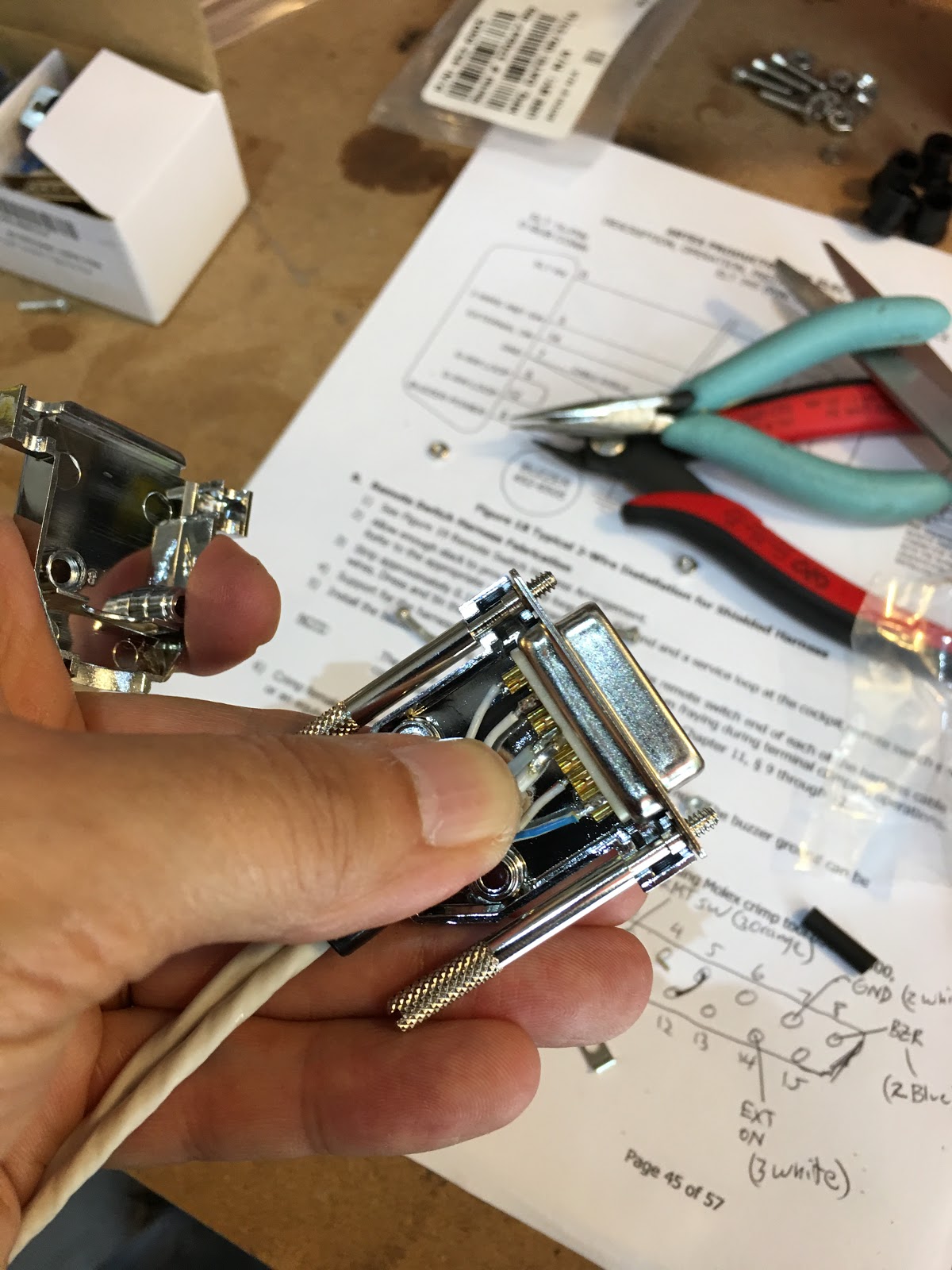
And it's done!

And in place!  I'll double check the wiring today with a meter.

Tuesday, August 22, 2017

I've been informed by the factory that if you have autopilot servos installed that the Garmin GMU 11 Magnetometer should be installed further back in the rear fuselage, so I'm looking into that (checking whether they have a mount, etc.).  It needs to be level with the fuselage, so it's not a trivial mount to construct.

Also, I read on another builder's blog (thanks JimP!) that the Krylon paints are much better than the Rustoleum, so I've gone ahead and ordered a box.  This is what I ordered.  I'll use that to paint the seats and anything else I think might have some visual exposure in the cockpit (or outside - e.g. front wheel strut).


Monday, August 21, 2017

1 hr. balancing the static port lines, routing it forward.

Cut the line coming from the left side to end in the middle top of the fuselage and used that cut piece to run the right side line to the same location.

Done!

And routed up to the front.  Plenty length to spare.

Put edge grommet in preparation for the wiring to the pitch servo.

And my wife and I climbed Mt. Washington in New Hampshire over the weekend.  The wind was gusting to 70 mph at the top.  This is the highest peak east of the Mississippi and the highest wind speed ever measured on Earth was here...  Tough climb in the howling wind...  Oh, and near zero visibility. :-O

Here's a video showing the wind as we neared the summit...


Thursday, August 17, 2017

Bummed that I haven't been able to work on the plane much lately....  Just too much going on.  Things should improve after this weekend and I'll be able to get back to making progress.

Also really want to get the information complete for the panel quote.  Once that's out then I can focus more too.

Friday, August 11, 2017

1.5 hrs. on COM2 and the rear seat.

Time to make the hole for the BNC connector of the antenna.  Drilled it first then used the grinder on the Dremel to take it to size.

Done!

Need to ream out the latch attachment holes to M4 rivnut size.

As you'll see in the next photo I found that the holes in the latch itself were wider apart then the seat's holes and the holes in the thick piece seen here.  I reamed the holes in the seat such that they were wider apart and also made the holes wider apart in the thick piece with a small reamer bit.  The arrow is pointing to the parts (basically all of those parts I'm holding) that will actually go outside the upholstery.

Here you can see the pitch difference.

And it fits!  Even though the upholstery will be under those parts, for now I will leave them like this so they don't get lost.

Done for the day and the work area all cleaned up!

I've added a new page that I will be using for my panel quoting and planning.  See it here.

If you go to my Avionics page there will be a link to it on that page too.


Wednesday, August 9, 2017

1.5 hr. on the COM2 antenna.

Parts I got yesterday.

Of course I didn't read the magnetometer installation manual before installing it...  But, I read it today and found that it must be square with the line of the aircraft.  I got lucky because it was perfect... :-/

Time to install the COM2 backing plate (this time I read the simple instructions!).

I want to make sure it's lined up with the center line so I drew a median down the plate.

Stretched a string down the center line....

But, I was extra paranoid, so I took multiple measurements to make sure it really was straight down the center line.

Now to line up the median and my center line.

Marked and double checked yet again...  It looks off in the photo because of the angle, but it was perfect.

Center punched carefully.

Checking again...

Photo got rotated, but here it is after I've drilled it with progressively larger bits.

The holes were M3 sized at this point so I put in my largest clecos to keep it lined up while I reamed the other holes to M4, my intended size.

Reamed to M4 and ready for the rivnuts.  Loctite 277 applied and ready to go...

Done and perfect! :-)  Now just have to drill out the center hole for the BNC connector and we're all set.  OK, near perfect.  One of the rivnuts didn't properly install because the plate came up a bit.  No matter though because the screw will go in just fine.